38 moment diagram examples
Share your videos with friends, family, and the world Bending Moment at XX is obtained by treating the load to the left of XX as a concentrated load of the same value (w.x) acting through the centre of gravity at x/2. S.F and B.M diagram Therefore, the bending moment at any cross-section XX is . 2.. x 22 x wx Mwx Therefore the variation of bending moment is according to parabolic law.
CE 331, Fall 2007 Shear & Moment Diagrams Examples 3 / 7 max MD = 16.0k-ft at Support 2 3. Calculate the max. moment due to live load (ML) at the location of the max. moment due to dead load (MD). 3.1 Determine where to place the live load to cause the max ML at the middle of Span 1. As mentioned on Page 1, the location of live loads is variable.

Moment diagram examples
Problem 6: Bending Moment Diagram Plot shear and bending-moment diagrams for a simply supported beam with a uniformly distributed load; see Figure. Figure Solution A section at a distance x from the left support is taken as shown in figure (b). The shear is found out by subtracting the load to the left of the section from the left upward reaction. That completes the moment diagram for this example. The maximum negative moment is -50 ft*lb at support A and the maximum positive moment is ~17.4 ft*lb to the left of support B. For structural problems it is common to use the opposite sign convention so that the graph of the final moment diagram resembles the flexure of the member. I may want ... Taking the moment about point C of the free-body diagram suggests the following: Free-body diagram of entire arch again. Bending moment at point Q: To find the bending moment at a point Q, which is located 18 ft from support A, first determine the ordinate of the arch at that point by using the equation of the ordinate of a parabola.
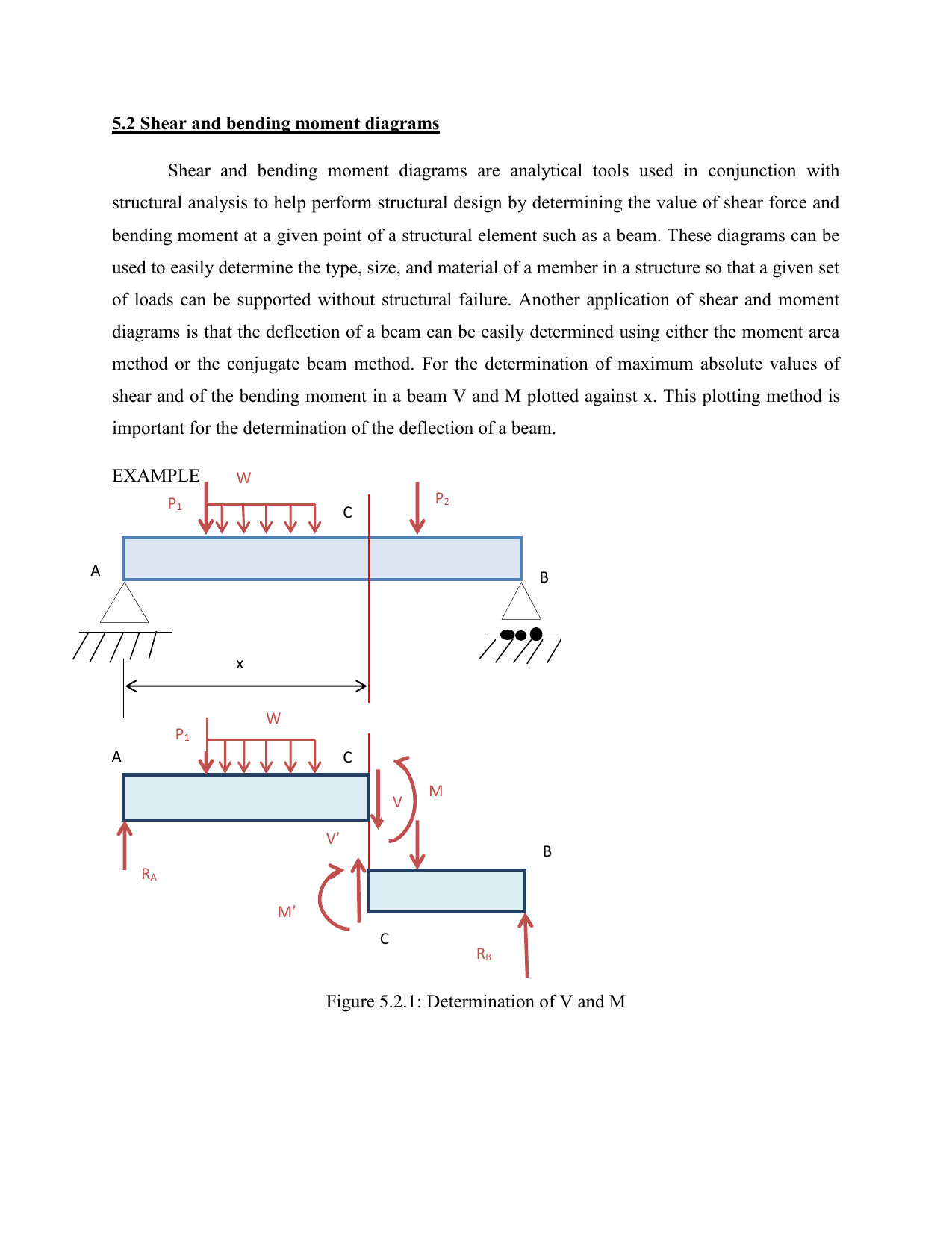
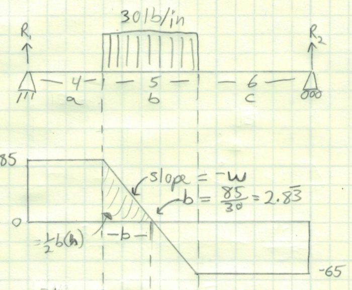
Moment diagram examples. BEAM DIAGRAMS AND FORMULAS Table 3-23 (continued) Shears, Moments and Deflections 13. BEAM FIXED AT ONE END, SUPPORTED AT OTHER-CONCENTRATED LOAD AT CENTER Shear and moment diagrams and formulas are excerpted from the Western Woods Use Book, 4th edition, and are provided herein as a courtesy of Western Wood Products Association. Introduction Notations Relative to "Shear and Moment Diagrams" E = modulus of elasticity, psi I = moment of inertia, in.4 L = span length of the bending member, ft. the shear and bending moment diagrams. 7 V and M are in the opposite directions of the positive beam sign convention. 8 Shear and Bending Moment Diagrams Zero Shear. Maximum. Positive. Bending. Moment ⇒ 9 Principle of Superposition. 10 Example Problem Shear and Moment Diagrams Calculate and draw the shear force and bending moment equations ... Shear and Moment Diagrams Consider a simple beam shown of length L that carries a uniform load of w (N/m) throughout its length and is held in equilibrium by reactions R1 and R2. Assume that the beam is cut at point C a distance of x from he left support and the portion of the beam to the right of C be removed. The portion removed must then be replaced by vertical shearing
Problem 403 Beam loaded as shown in Fig. P-403. [collapse collapsed title="Click here to read or hide the general instruction"]Write shear and moment equations for the beams in the following problems. In each problem, let x be the distance measured from left end of the beam. Also, draw shear and moment diagrams, specifying values at all change of loading positions and at Example of drawing a shear and moment diagram graphically for a simply supported beam with a concentrated moment and linearly distributed load. I recommend ... Basic Example to Construct a Shear and Moment Diagram : Constructing shear and moment diagrams is similar to finding the shear and moment at a particular point on a beam structure. However, instead of using an exact location, the location is a variable distance 'x'. Example 2. Simply supported beam calculation. Calculate the support reactions. Draw the Bending Moment diagram. Draw the Shear Force Diagram. Draw the Axial Force Diagram. More. Example 3. Cantilever beam calculation carrying a uniformly distributed load and a concentrated load.
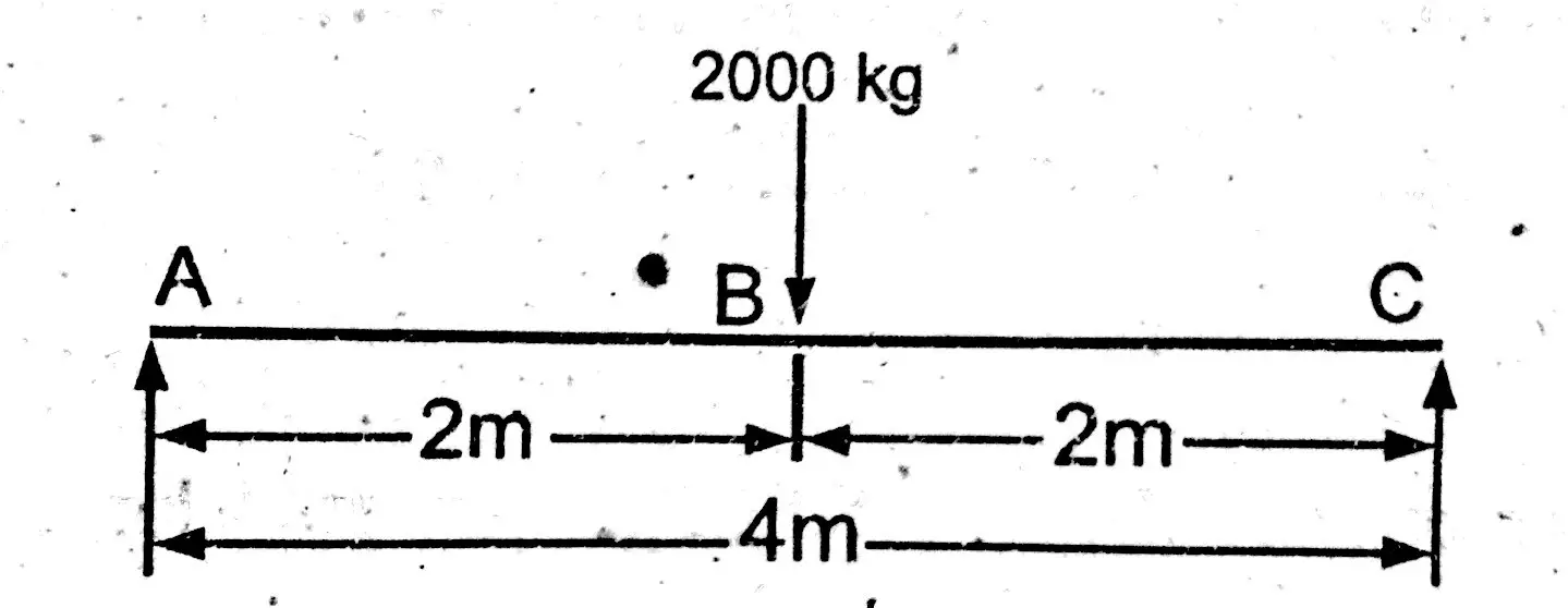
Bending moment at point B = M(B) = R1 x Distance of R1 from point B. Bending moment at point B = M (B) = 1000 x 2 = 2000 kg.m. Bending Moment Diagram Simply Support Beam with UDL & Point Load Example. Draw shear force and bending moment diagram of simply supported beam carrying uniform distributed load and point loads. As shown in figure. Solution Module 6 - Shear Force and Bending Moment Diagram Examples 6:02. Taught By. Dr. Wayne Whiteman, PE. Senior Academic Professional. Try the Course for Free. Transcript [MUSIC] Welcome to Module 6 of Mechanics of Materials Part III on Beam Bending. Today's learning outcomes are to finish up sketching the bending moment diagram for a multiforce ... Examples: Level 1: Single Point Load. This is example shows how to use the steps outlined in the "Steps" tab to draw shear force and bending moment diagrams. Level 2: Distributed Force. This example deals with a constant distributed force (shear is a linear function of x). Level 3: Point Moment. In this example, the point moment causes no shear ... ❑The weight of the beam is an example of distributed loading, but ... obtain the shear force and bending moment diagrams for the.42 pages
Mechanics Map Shear And Moment Diagrams
SHEAR FORCE DIAGRAMS MOMENT DIAGRAMS [EXAMPLES] • Equilibrium Method for V and M Diagrams • Semi-graphical Method for V and M Diagrams . Dr. Mohammed E. Haque, P.E. Lecture Notes COSC321Haque 2 PDF_C8_b (Shear Forces and Bending Moments in Beams) Equilibrium Method for V and M Diagrams Q1:
Shear Load And Bending Moment Diagrams
Plot the moment diagram starting from the left end. As you encounter changes in the shear diagram, draw the moment diagram as outlined in Note B. Label magnitude of the moment at the maximum and minimum points along the function as well as what point along the X axis they occur.

Shear Force And Bending Moment Diagram And Examples Pigso Learning
Objective: To explain the concept of Moment in Statics with everyday examples. Sign Convention for Moments - + Clockwise negative Anti-clockwise positive Objective: To illustrate the sign conventions for Moment in Statics. F d M = - F d What is the moment at A for the Noodle Beam fixed at A and
Theory C4 1 Shear Force And Bending Moment Diagrams Solid Mechanics I
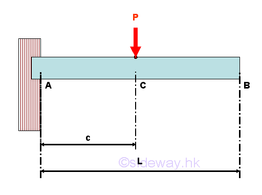
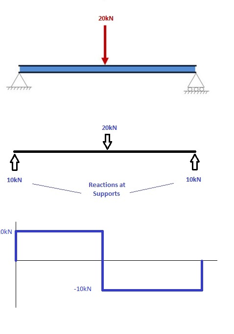
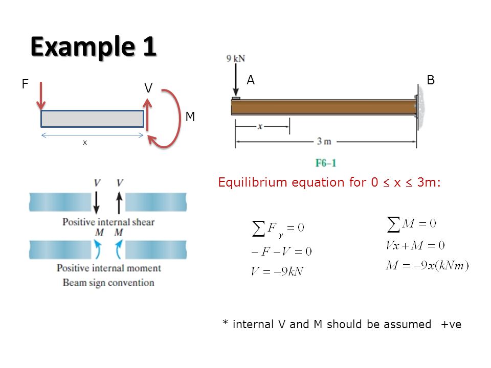
EXAMPLE 1 . Draw the free body diagram: By taking the moment at B, ... bending moment diagram (BMD). b) If P = 20 kN and L = 6 m, draw the SFD and BMD for the beam. P kN L/2 L/2 A B EXAMPLE 4 . P kN L/2 L/2 R Ax R Ay R By By taking the moment at A:
2
To calculate the bending moment of a beam, we must work in the same way we did for the Shear Force Diagram. Starting at x = 0 we will move across the beam and calculate the bending moment at each point. Cut 1. Make a "cut" just after the first reaction of the beam. In our simple example:

Bending Moment Diagram An Overview Sciencedirect Topics
4.0 Building Shear and Moment Diagrams. In the last section we worked out how to evaluate the internal shear force and bending moment at a discrete location using imaginary cuts. But to draw a shear force and bending moment diagram, we need to know how these values change across the structure.
Asm Example 2 Structnotes
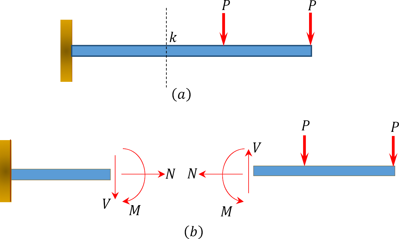
3.2 - Shear Force & Bending Moment Diagrams What if we sectioned the beam and exposed internal forces and moments. This exposes the internal Normal Force Shear Force Bending Moment ! What if we performed many section at ifferent values Of x, we will be able to plot the internal forces and bending moments, N(x), V(x), M(x) as a function Of position!
Example Direct Method C5 3 Shear Force And Bending Moment Diagrams Statics
Shear force and bending moment diagram example #4: applied moment; Shear force and bending moment diagram example #5: mixed distributed and point loads; The Quick Way To Solve SFD & BMD Problems. Shear force and bending moment diagram practice problem #1; Shear force and bending moment diagram practice problem #2

Drawing Shear Force Bending Moment Diagram File Exchange Pick Of The Week Matlab Simulink
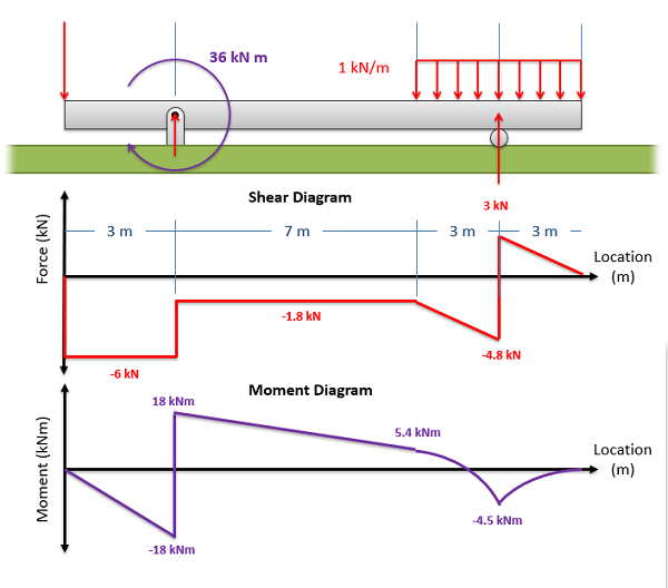
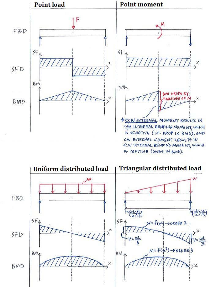
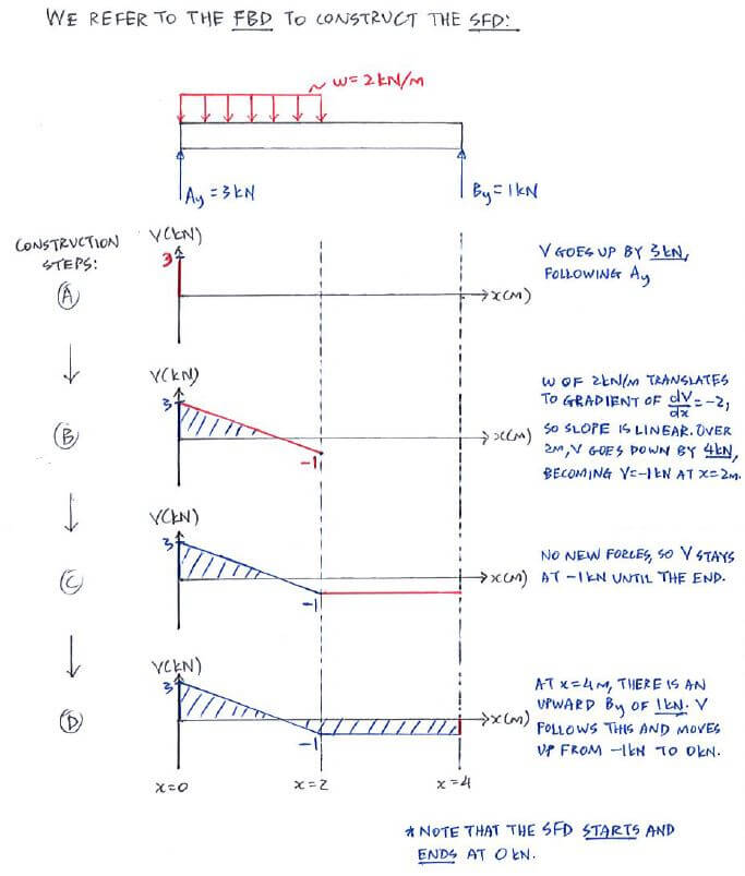
Shear Diagram: Moment Diagram: 1. Point loads cause a vertical jump in the shear diagram. The direction of the jump is the same as the sign of the point load. 2. Udl result in a straight, sloped line on the shear diagram. 3. The shear diagram is horizontal for distances along the beam with no applied load. 4.

Ultimate Guide To Shear Force And Bending Moment Diagrams Engineer4free The 1 Source For Free Engineering Tutorials
Using the Moment Area Theorems. The moment area theorems rely on the bending moment diagram, so at first this should have been determined. Secondly, drawing a rough sketch of the expected deflected shape of the structure proves quite helpful, because the methodology uses the the geometric relationships between slopes and deflections, that are specific to the examined structure.
1 4 Internal Forces In Beams And Frames Engineering Libretexts
Diagrams. Shear force and bending moment are examples of interanl forces that ... A bending moment diagram is one which shows variation in bending moment ...9 pages
How To Draw Shear Force Bending Moment Diagram Simply Supported Beam Examples Engineering Intro
Shear Moment Diagram Examples. chapter 2 shear force and bending moment draw the shear force and bending moment diagrams shear force & bending moment example 1 draw the free body diagram by taking the moment at b shear and moment diagrams shear and moment diagrams consider a simple beam shown of length l that carries a uniform load of w n m throughout its length and is held in equilibrium
5 2 Shear And Bending Moment Diagrams W Shear And Bending
example v m diagrams part 1 constant shear force again the bending moment graph is continuous at x = 7 m the jump in the shear force at x = 7 m causes the slope of the bending moment to change suddenly from dm dx = v = 26 kn·m m to dm dx = 19 kn·m m. Figure 5 1 3 1 and of the seismic action are carried by the strong column 800 400 and the ...
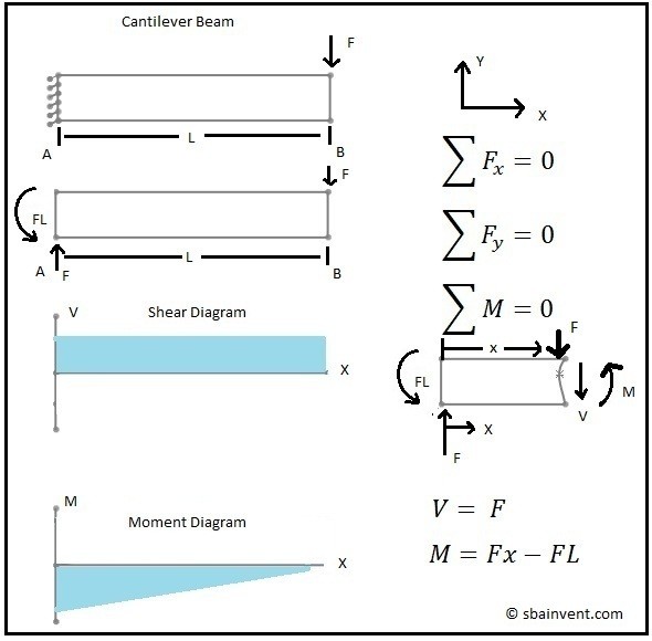
Shear And Moment Diagrams S B A Invent
68. Shear force and bending moment diagram example #1: single point load 69. Shear force and bending moment diagram example #2: multiple point loads 70. Shear force and bending moment diagram example #3: distributed loads 71. Shear force and bending moment diagram example #4: applied moment 72.

Bending Moment Diagram An Overview Sciencedirect Topics
Taking the moment about point C of the free-body diagram suggests the following: Free-body diagram of entire arch again. Bending moment at point Q: To find the bending moment at a point Q, which is located 18 ft from support A, first determine the ordinate of the arch at that point by using the equation of the ordinate of a parabola.
1
That completes the moment diagram for this example. The maximum negative moment is -50 ft*lb at support A and the maximum positive moment is ~17.4 ft*lb to the left of support B. For structural problems it is common to use the opposite sign convention so that the graph of the final moment diagram resembles the flexure of the member. I may want ...
Bending Moments And Shearing Forces In Beams Case 2
Problem 6: Bending Moment Diagram Plot shear and bending-moment diagrams for a simply supported beam with a uniformly distributed load; see Figure. Figure Solution A section at a distance x from the left support is taken as shown in figure (b). The shear is found out by subtracting the load to the left of the section from the left upward reaction.
What Is Shear Force And Bending Moment And Why Do We Need To Calculate Them Quora
1
Moment Diagrams Examples
Determining The Shear Force And Bending Moment Equations Of Simply Supported Beam
Shear And Bending Moment Problems Civil Engineering
2
2

Shear Force And Bending Moment Diagrams Wikiversity
Shear Moment Diagrams The Best Guide To Using Them Mentored Engineer
How To Find Out The Concavity Of Shear Force And Bending Moment Diagram Quora
Moment Diagram Physics Forums

Shear Force And Bending Moment Diagram And Examples Pigso Learning

Moment Diagrams Examples
Shear And Bending Moment Diagrams Of Concentrated Applied Loads 27 11 Sideway Output To
How To Calculate Bending Moment Diagram Skyciv
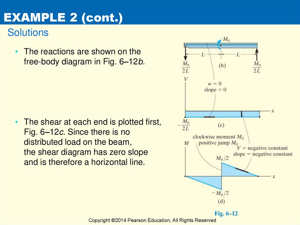
Unit 6 Bending Shear And Moment Diagrams Online Presentation
Civil Engineering Solved Examples For Shear Force And Bending Moment Diagram
21 B Example 18 For The Given Frame In 22 A Draw The Normal Shear Download Scientific Diagram
Bending Shear And Moment Diagram Graphical Method To Construct Shear Ppt Download
Solved Draw The Shear Force Diagrams And The Bending Moment Chegg Com

Shear Force And Bending Moment Diagrams Wikiversity


Komentar
Posting Komentar