43 signal flow diagram
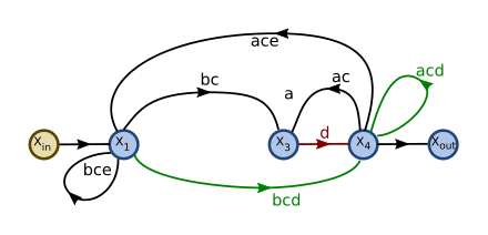
Rotational Mechanical Systems Block Diagrams Signal Flow Graph Method Signal Flow Graph-Cont. Algebra of SFG: 1 Output variable of a node = weighted sum (by the gains of branches) of all incoming branches. x 2 = ax 1, x 3 = bx 2 ex 4, x 4 = cx 3 + fx 2, x 5 = dx4 2 Parallel branches Note: all branches must be in same direction (otherwise they form a loop). signal flow graph is used to represent the control system graphically and it was developed by s.j.mason.signal flow graph is a diagram that represents a set of simultaneous linear algebraic equations.by differential equations governing a control system can be algebraic equations in s-domain.the signal flow graph of the system can be constructed …
So, to overcome this drawback, use signal flow graphs (representation). In the next two chapters, we will discuss about the concepts related to signal flow graphs, i.e., how to represent signal flow graph from a given block diagram and calculation of transfer function just by using a gain formula without doing any reduction process.

Signal flow diagram
Introduction 3 • A signal-flow graph consists of a network in which nodes are connected by directed branches. • It depicts the flow of signals from one point of a system to another and gives the relationships among the signals. 4. Analog I/Q Modulation-Transceiver • I/Q signals take on a continuous range of values (as viewed in the time domain) • Used for AM/FM radios, television (non-HDTV), and the first cell phones • Newer systems typically employ digital modulation instead Receiver Output 2cos(2πf 1t) 2sin(2πf 1t) Lowpass i r(t) Lowpass q r(t) i t q t 2cos ... Signal Flow. This course will present the fundamentals of musical harmony in contemporary western tradition. Through written text, diagrams, and high-resolution video demonstrations, this course aims to demystify the harmonic foundations of music for aspiring players and songwriters. You will analyze the simple chord structures in many hit ...
Signal flow diagram. Control Systems- Block Diagrams and Signal Flow Graphs . The block diagram modeling may provide control engineers with a better understanding of the composition and interconnection of the components of a system.; It can be used, together with transfer functions, to describe the cause-effect relationships throughout the system.The common elements in block diagrams of most control systems include: A signal flow graph is usually obtained from the block diagram of the system. They can also be obtained directly from the system equations, but for now we shall stick with the former approach. We shall follow a few rules while trying to obtain a SFG from a block diagram of a system. You break out the manual. It will contain what is typically called a "block diagram". Now block diagrams can be headache-inducing nightmares. Check out this one for a Yamaha DM2000: So I recommend that you take the time to create your own simplified signal flow. Just follow the lines on the block diagram to determine the signal path. 1.0 Given a block diagram, print, or schematic, IDENTIFY the basic component symbols as presented in this module. ENABLING OBJECTIVES 1.1 IDENTIFY the symbols used on engineering electronic block diagrams, prints, and schematics, for the following components. a. Fixed resistor o. Fuse b. Variable resistor p. Plug c. Tapped resistor q. Headset d.
Signal flow diagram illustrating the path that a signal follows in a typical PA system. An input device is the interface between a sound source and the sound system. In most cases, it will consist of either a microphone or a direct input (DI) box. S.ignal flow graphs are a viable alternative to block diagrammatic representation of a system. What makes SIgnal flow graphs attractive is that certain features from graph theory can be applied to the simplification and the synthesis of complex systems. 100.1 Introduction First, what is a signal flow diagram, and why do I need it? A signal flow diagram shows the signal path (audio, video, network, control, etc.) from inputs to outputs, for the entire AV system. It's essentially a blueprint for the system… and would you buy a house where they didn't have a blueprint? Q. Signal flow graphs: A. they apply to linear systems: B. the equation obtained may or may not be in the form of cause or effect: C. arrows are not important in the graph: D. they cannot be converted back to block diagram: Answer» a. they apply to linear systems: Explanation: signal flow graphs are used to find the transfer function of ...
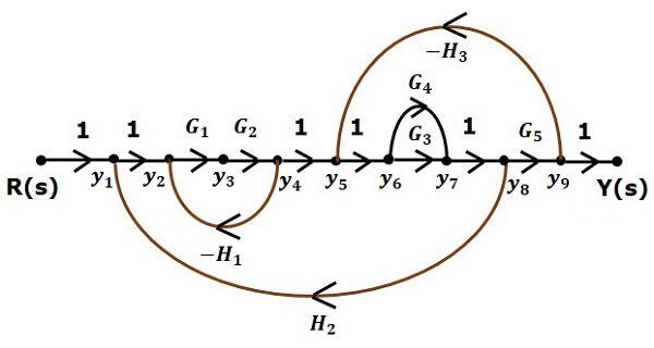
Signal-flow graphs in the time and frequency domains. The signal-flow graph is a structural description of the algorithm in terms of its operations and their ordering, whereas the transfer function is a behavioral description. Systematic procedures for deriving the transfer function are given in [ 32, 40 ]. View the full answer. Transcribed image text: Convert the following block-diagram to a signal flow graph, then apply Mason's rule to find the Y (s)/R (s). H, R (S) + Y (S) G G G G Н. H H2 Н. Signal flows in one direction, from the presynaptic neuron to the postsynaptic neuron via the synapse which acts as a variable attenuator. A simplified diagram of a synapse is shown in Fig. 1.16A [20]. As an element of neural circuits, it is a "two-terminal device." Sign in to download full-size image Figure 1.16. A graphical method of representing the control system using the linear algebraic equations is known as the signal flow graph. It is abbreviated as SFG. This graph basically signifies how the signal flows in a system. The equation representing the system holds multiple variables that perform a crucial role in forming the graph.
Control Systems Signal Flow Diagrams Wikibooks Open Books For An Open World
Control Flow = flow of functional behaviors; Object Flow = data flow of object inputs/outputs into/from an Activity or Action. Activity diagram (act): An Activity diagram shows system dynamic behavior using a combined Control Flow and Object (data) Flow model.
Signal Flow Graph
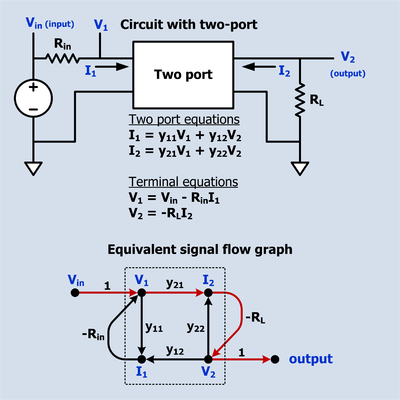
Fundamentals of Signal Flow Graphs •Consider a simple equation below and draw its signal flow graph: •The signal flow graph of the equation is shown below; •Every variable in a signal flow graph is designed by a Node. •Every transmission function in a signal flow graph is designed by a Branch. •Branches are always unidirectional.
Signal Flow Graph Wikipedia
To make things easier for you, we're tackling the basics of mixing console signal flow. The Function Of A Mixing Console A mixing console allows you to feed your recorded signal into your DAW and then monitor the sound as a full mix via the console faders .
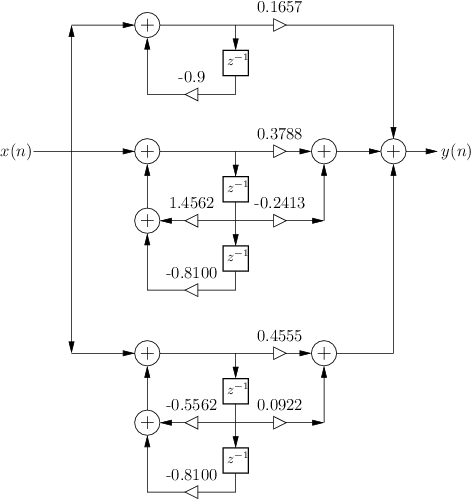
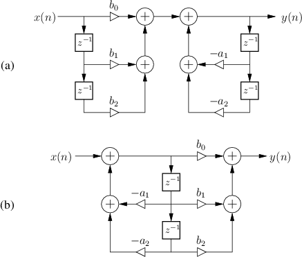
Parallel Second Order Signal Flow Graph Introduction To Digital Filters
Signal Flow Graph (SFG) Introduction: Block diagram reduction is the excellent method for determining the transfer function of the control system.However, in a complicated system, it is very difficult and time-consuming process that is why an alternate method, i.e., SFG was developed by S.J Mason which relates the input and output system variables graphically.
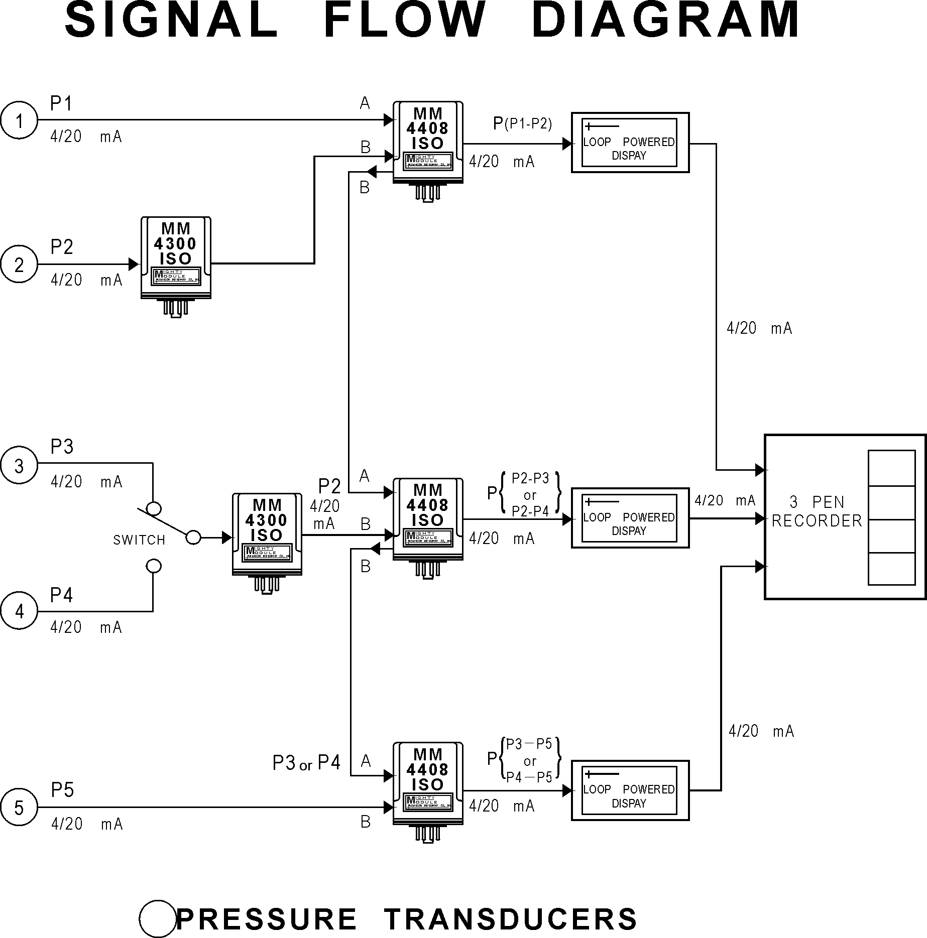
Wilkerson Instrument Company Inc Blog 20801 Signal Flow Diagram
A signal-flow graph or signal-flowgraph ( SFG ), invented by Claude Shannon, but often called a Mason graph after Samuel Jefferson Mason who coined the term, is a specialized flow graph, a directed graph in which nodes represent system variables, and branches (edges, arcs, or arrows) represent functional connections between pairs of nodes.

Signal Flow Graph And Effects Of Feedback Geeksgod
Quadrature (Q) signal in the CW path to present the direction and speed of blood flow. Figure 2. CW Doppler Receiver Chain Signal Conditioning The typical post-treatment circuit of I and Q signal usually consists of a simple R-C summing stage, two high-speed driver amplifiers, and two high-precision ADCs. Figure 2 shows the typical block ...
Transaudiogroup Com
3/13/2009 Signal Flow Graphs 1/12 Jim Stiles The Univ. of Kansas Dept. of EECS Signal Flow Graphs Consider a complex 3-port microwave network, constructed of 5 simpler microwave devices: where S n is the scattering matrix of each device, and S is the overall scattering matrix of the entire 3-port network. Q: Is there any way to determine this overall network

Signal Flow Graphs 1 5 Tutorials Circuitbread
Signal Flow Graphs An alternative to block diagrams for graphically describing systems Signal flow graphs consist of: Nodes–represent signals Branches–represent system blocks Branches labeled with system transfer functions Nodes (sometimes) labeled with signal names

Signal Flow Graph Wikipedia
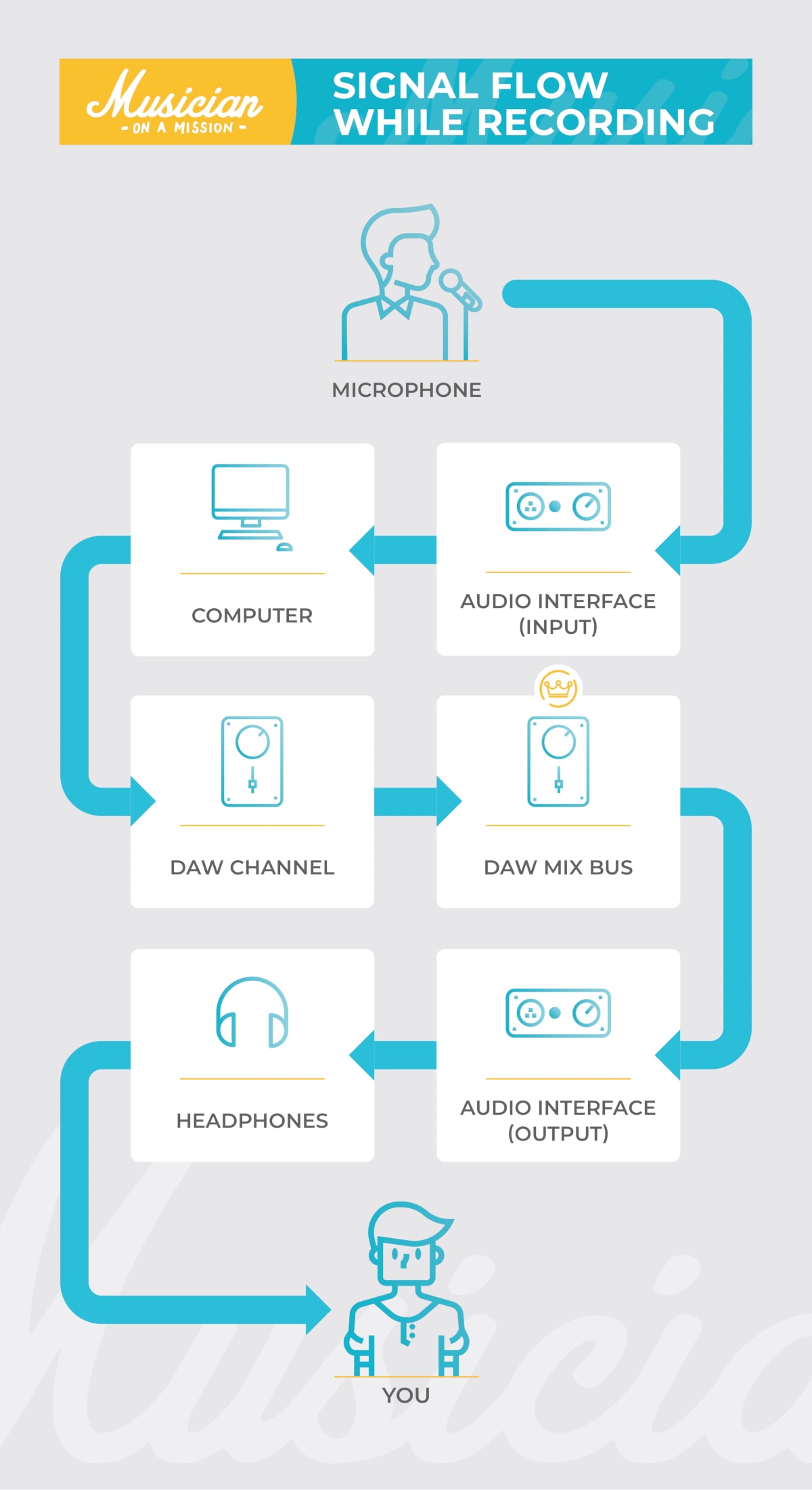
A step by step walk through the diagram. 1. Microphone->Mic Preamp. The microphone picks up the sound, and a mic level signal is sent to the microphone preamp. Since mic level signals are inherently weak, the preamp is needed to amplify it to a higher level. The amplified signal is known as line level. 2.
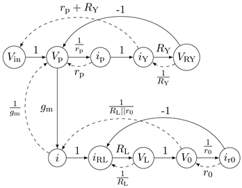
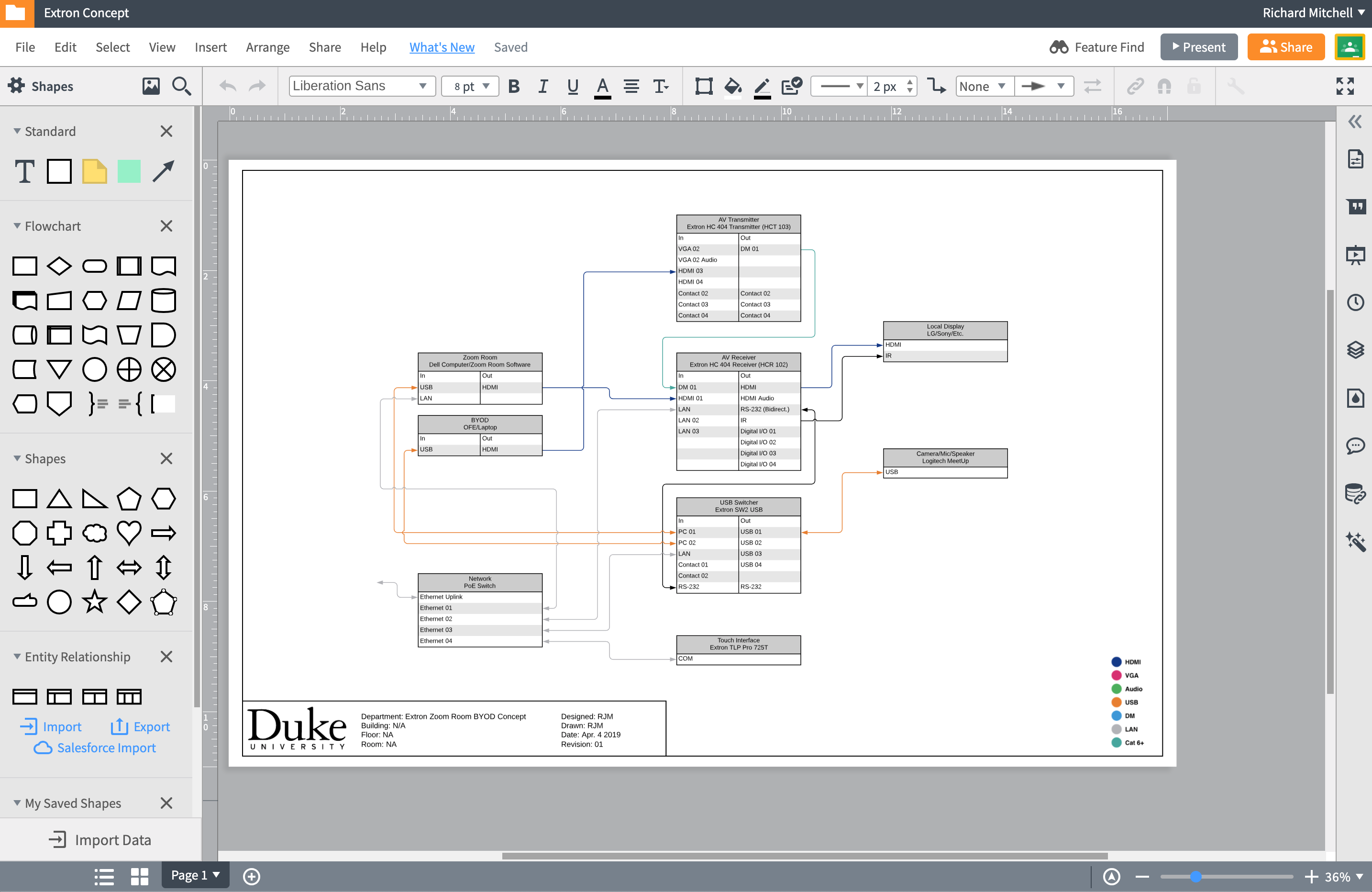
Analysis Of Electronic Circuits With The Signal Flow Graph Method
From simple to complex, the ConnectCAD add-on to Spotlight and Design Suite gives AV system designers the power to lay out signal flows in an easy-to-read format.

Gate 2011 Ece Find Signal Flow Graph From Given Transfer Function Of Unity Negative Feedback System Youtube
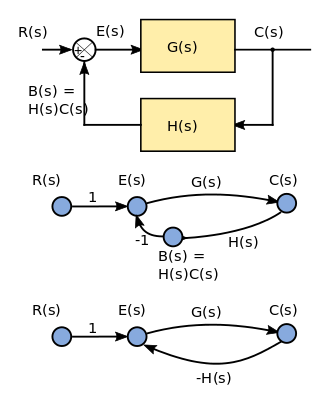
Signal-flow graphs are an alternative to block diagrams. Signal flow graphs are a pictorial representation of the simultaneous equations describing a system. Signal flow graphs display the transmission of signals through the system, as does the block diagrams, but it is easier to draw and easier to manipulate than the block diagrams.

Signal Flow Diagrams Acid Pro
Overview diagram of Signal Flow for this example. The house sound system will be controlled from the "Front of House" position, also called the "Mix position." This position is usually located behind the audience. The view from the Front of House Position.

Audio Signal Flow Wikipedia
Q. Signal flow graphs is. answer choices. They apply to linear systems. The equation obtained may or may not be in the form of cause or effect. Arrows are not important in the graph. They cannot be converted back to block diagram. <p>They apply to linear systems</p>. alternatives.
Signal Flow Graph Introduction To Digital Filters
Step 6 − Signal flow graph of overall system is shown in the following figure. Conversion of Block Diagrams into Signal Flow Graphs. Follow these steps for converting a block diagram into its equivalent signal flow graph. Represent all the signals, variables, summing points and take-off points of block diagram as nodes in signal flow graph.

Signal Flow Signature Sound
Signal flow graph of control system is further simplification of block diagram of control system. Here, the blocks of transfer function, summing symbols and take off points are eliminated by branches and nodes. The transfer function is referred as transmittance in signal flow graph. Let us take an example of equation y = Kx.

Signal Flow
What Is Signal Flow? Signal flow is the order of operations a sound goes through. When you record an instrument, the sound goes through different stages before you hear it through the speakers. Signal flow is the list of steps that sound goes through in order for you to hear it. It's kind of like riding a train. Say you're trying to get downtown.

Signal Flow Graph Representation Of The Rls Algorithm Download Scientific Diagram
Signal Flow. This course will present the fundamentals of musical harmony in contemporary western tradition. Through written text, diagrams, and high-resolution video demonstrations, this course aims to demystify the harmonic foundations of music for aspiring players and songwriters. You will analyze the simple chord structures in many hit ...
Audio Signal Flow What It Is And How To Use It
Analog I/Q Modulation-Transceiver • I/Q signals take on a continuous range of values (as viewed in the time domain) • Used for AM/FM radios, television (non-HDTV), and the first cell phones • Newer systems typically employ digital modulation instead Receiver Output 2cos(2πf 1t) 2sin(2πf 1t) Lowpass i r(t) Lowpass q r(t) i t q t 2cos ...

Generic Signal Flow Diagram Download Scientific Diagram
Introduction 3 • A signal-flow graph consists of a network in which nodes are connected by directed branches. • It depicts the flow of signals from one point of a system to another and gives the relationships among the signals. 4.
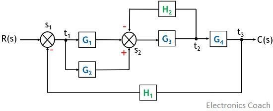
Signal Flow Graph Of Control System Properties And Methods Of Obtaining Signal Flow Graph Electronics Coach

Signal Flow Diagram Quizlet
1

Signal Flow Diagram For Manual And Pilot In The Loop Mode Download Scientific Diagram

Ann Jusdl Jl V0 1 2 Signal Flow Graphs Detecting And Breaking Algebraic Loops Package Announcements Julialang
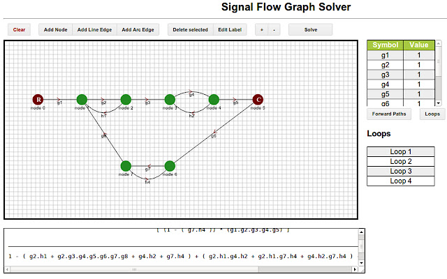
Control Systems Signal Flow Graphs

Analog Recording Signal Flow Diagrams How Does It Work
Control Systems Signal Flow Diagrams Wikibooks Open Books For An Open World
Control Systems Signal Flow Graphs
1
Signal Flow Graph Wikipedia
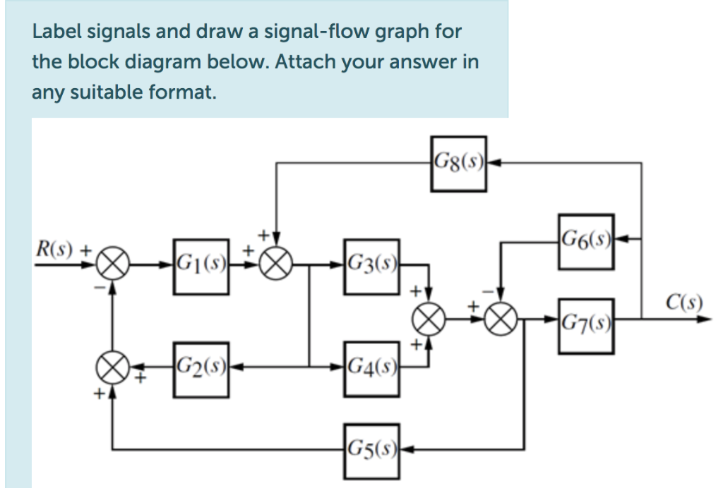
Solved Label Signals And Draw A Signal Flow Graph For The Chegg Com

File Block Diagram Signal Flow Graph Svg Wikimedia Commons

Signal Flow Diagram The Music District

Signal Flow Graph Representation Of Lms Algorithm Download Scientific Diagram

Understanding Signal Flow Soundsessions

Signal Flow Graphs 1 5 Tutorials Circuitbread
Quick Av Signal Flow With Lucidchart Ddmc

The Ins And Out Of Audio Signal Paths Live Sound Education
Signal Flow Graph Wikipedia

2 15 Reduction Of The Signal Flow Graph Modern Control System Theory And Design 2nd Edition Book

Building A Signal Flow Diagram

Signal Flow Diagrams Smartsdr Wiki
Control Systems Signal Flow Graphs


Komentar
Posting Komentar