40 ram circuit diagram
I'm looking at "[https://www.allaboutcircuits.com/technical-articles/implementing-multiplexers-with-pass-transistor-logic](https://www.allaboutcircuits.com/technical-articles/implementing-multiplexers-with-pass-transistor-logic)" with title "Implementing Multiplexers with Pass-Transistor Logic" by Robert Keim. Under label "The Transmission Gate Multiplexer" I see the circuit diagram I'm adding in the comments. Is it unreasonable to assume a five volt value for logic one and a zero volt value for... Here are a number of highest rated 2015 Dodge Ram 1500 Lifted pictures on internet. We identified it from trustworthy source. Its submitted by processing in the best field. We believe this nice of 2015 Dodge Ram 1500 Lifted graphic could possibly be the most trending subject as soon as we allocation it in google pro or facebook.
PDC is a printed circuit board-based module that contains fuses and relays, while the FCM contains the electronics controlling the IPM and other functions. fuse box diagram (2002-2005). Assignment of the fuses (2002-2005).

Ram circuit diagram
Apr 22, 2016 · It includes 8kB Flash memory, 256-byte EEPROM, 368-byte RAM, 33 input/output (I/O) pins, 10-bit 8-channel analogue-to-digital converter (ADC), three timers, watchdog timer with its own on-chip crystal oscillator for reliable operation, and synchronous I2C interface. Fig. 2: Circuit diagram of the digital temperature controller May 22, 2015 · Circuit Diagram and Explanation PIRs takes some time to stable itself according to surrounding conditions, so you can find, LED turn ON and OFF randomly for about 10-60 seconds. Now when we find the LED blinking whenever there is any motion, look back of the PIR, you will find a jumper which is placed between outer corner PIN and middle PIN ... Hey everyone So Im currently modifying a vintage Yamaha keyboard. I discovered that by connecting 2 points on the circuitboard, I can trigger a persistent click, kind of like a metronome, while the drum machine is on. I wired this to a simple toggle switch to turn it on and off. Flipping it up and down rapidly works as a sort of “drum fill” function, but its not an ideal solution. The force of flipping the switch on and off is causing wear and tear. So what id like to do is wire a momentary ...
Ram circuit diagram. May 22, 2017 · LCD display is an inevitable part in almost all embedded projects and this article is about interfacing a 16×2 LCD with 8051 microcontroller.Many guys find it hard to interface LCD module with the 8051 but the fact is that if you learn it properly, its a very easy job and by knowing it you can easily design embedded projects like digital voltmeter / ammeter, digital clock, home automation ... In computing, a northbridge, (also host bridge, or memory controller hub) is one of two chips comprising the core logic chipset architecture on a PC motherboard.A northbridge is connected directly to a CPU via the front-side bus (FSB) to handle high-performance tasks, and is usually used in conjunction with a slower southbridge to manage communication between the CPU and other parts of the ... Mar 21, 2016 · In this circuit a timer with cyclic on off operations is designed. This circuit uses very basic components like 555 timer and 4017 counter. These on off intervals can be adjusted by varying the 555 timer output and number of counter outputs. Let us discuss in detail about this circuit. Circuit Diagram I am trying to make a magic system which relies on magic circles, magic language, grimoires, geometry, etc... for a game. So I want to be a bit puzzle-like, easily understandable yet quite versatile. My idea was to make them like Electronic Circuits, with a magic source representing a battery or an AC source, some parafernalia in the middle that transforms magic energy into other types of energy(maybe elemental magics since I want my system to be elemental) then ground it. Since Electron...
Hello, I’m very new to circuit design and I’m trying to copy a circuit on a pcb that I have into a circuit diagram so I can better understand it. Doing this has been extremely hard. I’ve just been trying to copy over the exact trace layout onto a piece of paper but i’m unable to mark the components and it’s extremely messy. Should I suck it up and just try harder or is there an easier way to do this? Thanks Hkr 15c Wiring Diagram- One of the most difficult automotive repair tasks that a mechanic or repair shop can bow to is the wiring, or rewiring of a car's electrical system.The misfortune essentially is that every car is different. gone maddening to remove, replace or repair the wiring in an automobile, having an accurate and detailed hkr 15c wiring diagram is critical to the feat of the ... Listed below is the vehicle specific wiring diagram for your car alarm, remote starter or keyless entry installation into your 2004-2005 Dodge Ram .This information outlines the wires location, color and polarity to help you identify the proper connection spots in the vehicle. Read Or Download Gallery of ceiling fan light switch wiring diagram ceiling fan light - Electrical Dimmer Switch | pin by linecad on electrical symbol floor plan symbols, dodge ram switch panel install driven to wander,
Shop Holley at Summit Racing now! Legendary Holley carburetors have powered professional racers to victory for years, and you can bolt the same technology onto your engine. Every Holley carb is built in the USA and 100-percent flow tested for no-hassle, out-of-the-box performance. Holley fuel pumps, fuel injectors, throttle bodies, and EFI ... Hey everyone So Im currently modifying a vintage Yamaha keyboard. I discovered that by connecting 2 points on the circuitboard, I can trigger a persistent click, kind of like a metronome, while the drum machine is on. I wired this to a simple toggle switch to turn it on and off. Flipping it up and down rapidly works as a sort of “drum fill” function, but its not an ideal solution. The force of flipping the switch on and off is causing wear and tear. So what id like to do is wire a momentary ... May 22, 2015 · Circuit Diagram and Explanation PIRs takes some time to stable itself according to surrounding conditions, so you can find, LED turn ON and OFF randomly for about 10-60 seconds. Now when we find the LED blinking whenever there is any motion, look back of the PIR, you will find a jumper which is placed between outer corner PIN and middle PIN ... Apr 22, 2016 · It includes 8kB Flash memory, 256-byte EEPROM, 368-byte RAM, 33 input/output (I/O) pins, 10-bit 8-channel analogue-to-digital converter (ADC), three timers, watchdog timer with its own on-chip crystal oscillator for reliable operation, and synchronous I2C interface. Fig. 2: Circuit diagram of the digital temperature controller
1999 Dodge Cummins Ecm Wiring Diagram Download

2007 Dodge Ram Trailer Wiring Diagram | Trailer Wiring ...

Audi WEC No.7

2003 Dodge Ram 2500 Trailer Wiring Diagram Download

1998 Dodge Ram 1500 Radio Wiring Diagram For Your Needs

2013 Ram 1500 Wiring Diagram For Your Needs

1999 Dodge Ram 1500 Power Window Wiring Diagram - Wiring ...

2001 Dodge Ram 1500 Headlight Wiring Diagram Pics - Wiring ...

2001 Dodge Ram 2500 Stereo Wiring Diagram Collection ...

1996 Dodge Ram 2500 Wiring Diagram For Your Needs

Serial NVSRAM Circuit Diagram

Image from page 354 of "The street railway review" (1891)

Get 1994 Dodge Ram Wiring Diagram Sample

2001 Dodge Ram Wiper Wiring Diagram

Red Porsche GT4 at Circuit Paul Ricard (french track) - 3

Wiring Diagram For 2001 Dodge Ram 2500 - Readingrat ...

2004 Dodge Ram 1500 Wiring Diagram | Free Wiring Diagram
2010 Dodge Ram 1500 Abs Wiring Diagram - Wiring Diagram

2016 Dodge Ram Trailer Wiring Diagram Download

2005 Dodge Ram 1500 Tail Light Wiring Diagram - Wiring Forums
2005 Dodge Ram Infinity Stereo Wiring Images - Wiring ...

85 Dodge Ram Wiring Schematic
2001 Dodge Ram 1500 Radio Wiring Diagram - Cadician's Blog

2003 Dodge Ram 1500 Radio Wiring Diagram Images | Wiring ...
2014 Ram 1500 Radio Wiring Diagram - Cadician's Blog

2004 Dodge Ram 1500 Wiring Diagram — UNTPIKAPPS
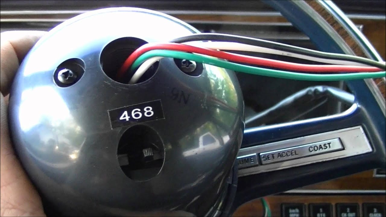
How To Install A Tachometer. - YouTube

Bablu Patel: RAM Section Circuit Diagram and Its Problem ...

2006 Dodge Ram Radio Wiring Diagram Pics | Wiring Collection

95 Dodge Ram 1500 Headlight Switch Wiring Diagram ...

2001 Dodge Ram 2500 Radio Wiring Diagram | Free Wiring Diagram

2003 Dodge Ram 2500 Wiring Diagram Pics - Wiring Diagram ...

2009 Dodge Charger Wiring Diagram | Dodge charger, Dodge ...

Wiring Diagram For 1994 Dodge Ram 1500

2003 Dodge Ram 3500 Tail Light Wiring Diagram - Wiring Diagram
ASUS How-To - Install CPU, CPU Fan, & Memory - YouTube

Get 1994 Dodge Ram Wiring Diagram Sample

2001 Dodge Ram 2500 Cruise Control Wiring Diagram Images ...

2015 Dodge Ram 1500 Trailer Ke Wiring Diagram | schematic ...

Dodge Ram 2500 Truck Wiring Diagram - HAISAYACARLMILIA


Komentar
Posting Komentar