41 time clock wiring diagram
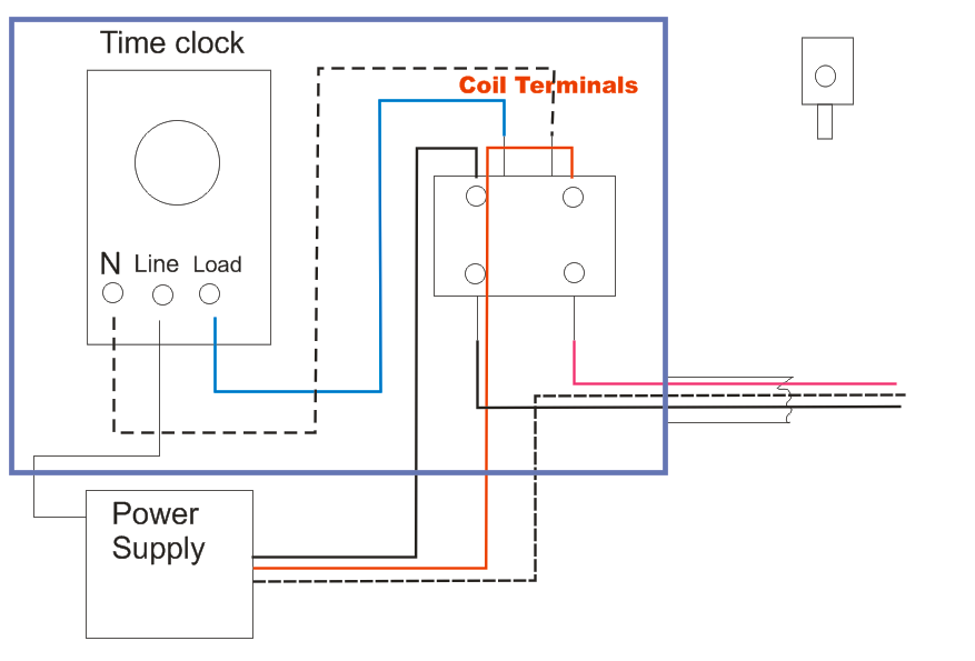
2. The line terminal of the time clock. (Clock motor is connected to same constant power as the P/C) The load side of the time clock runs to contactor(s) for fixtures that are meant to shut off at a specified time. Operation Scenario: All lights come on with P/C simultaneously (T/C set at 3PM). Bells may be arranged either on 110 volt current or on the storage battery voltage used by the master clock system. Jeffrey R. Wood. Wiring diagram for a SETco Clock System installed at the Southampton, New York High School in 1923/24. The High School became the Southampton Town Hall in 1970 and the clock must have been removed about that time.
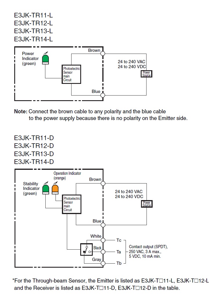
Page 6 of 16 November 2016 ProxPro Wiegand/Clock-and-Data Installation Guide, 5355A-900, Rev. N.3 3 Wiring 3.1 Standard Wire Connections TB1

Time clock wiring diagram
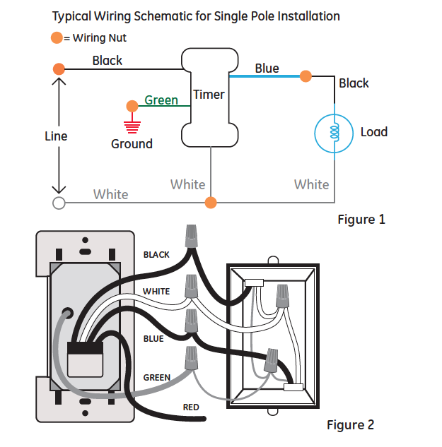
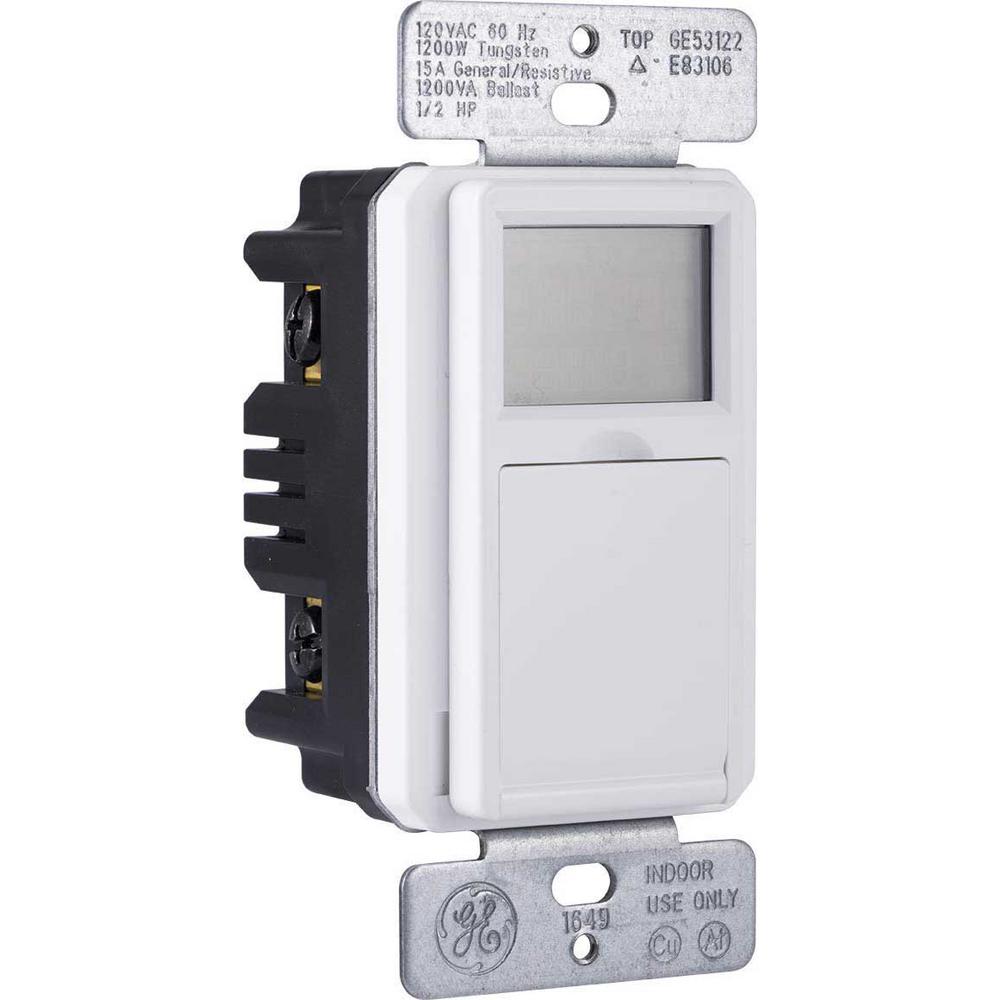
The next step in wiring the time switch is to connect the neutral wires. Cut an 8-inch length of white insulated wire as a pigtail, then strip 1/2 inch of insulation from each end. Insert one bare end of the pigtail into the neutral screw terminal on the switch and tighten the screw. This terminal may be marked NEUTRAL, or it may be indicated ... Put the time clock contacts AFTER the photocontrol in series with the red lead. Set the time clock to come on during daylight and off at 3AM. Photocontrols need to be hot all the time. In operation, photocontrol turns on the lights at dusk (time clock is already on) then the time clock turns them off at 3AM. -Hal In this video I will go over the Defrost time clock Wiring and Troubleshootinghttps://www.facebook.com/RKETEC/
Time clock wiring diagram. tork time clock wiring diagram - What is a Wiring Diagram? A wiring diagram is a straightforward visual representation with the physical connections and physical layout of an electrical system or circuit. It shows how a electrical wires are interconnected and will also show where fixtures and components might be attached to the system. Oct 21, 2017 · I Have 3 400 Watt Mh Lights 208 Volts That Want To On A Time Clock And Photo Cell Come At Dusk. How to wire a time clock wiring diagram electrician talk lighting contactors and i need you verify some things for me netss windsurfing css grudging photocell with on control install an analog switch does this circuit work thermostat override fan controller photocells timers electrical 101 trigger ... Tork Time Clock Wiring Diagram Sample. tork time clock wiring diagram - A Novice s Guide to Circuit Diagrams An initial take a look at a circuit representation may be confusing, yet if you can read a subway map, you could review schematics. The function is the same: obtaining from point A to direct B. Literally,… 3 3/8" Clock Wiring 1) Always disconnect the ground lead from the vehicle battery before wiring any gauge. 2) Connect a constant +12VDC source to terminal "3" on the back of the clock. 3) Connect a good ground to terminal "6" on the back of the clock. 4) Connect dash light power to terminal "7" on the back of the clock. 5) Connect ...
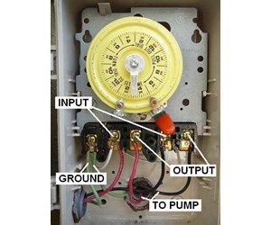
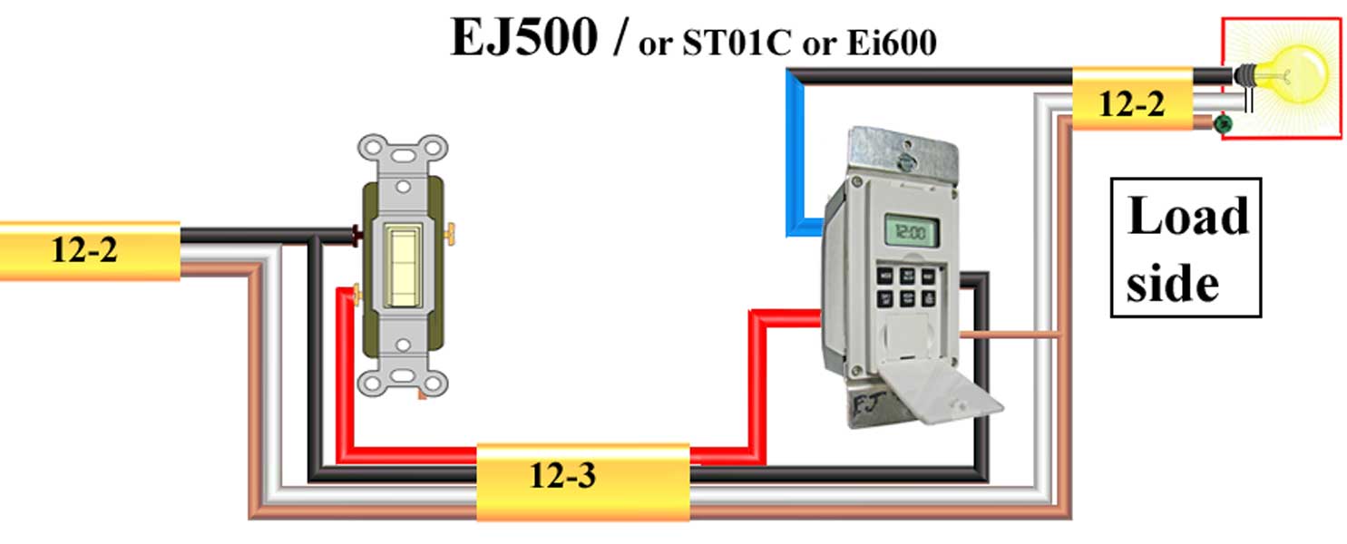
Step 7. Route the uninsulated ground wires from both wire sets along the timer's housing to the Intermatic timer's ground screw, located on the plate holding the timer's dial. Keep the ground wires clear of the "Line" and "Load" wire terminals. Description : Lighting, Contactors , Time Clock And Photo Cell. - Electrician in Photocell And Timeclock Wiring Diagram, image size 933 X 749 px, and to view image details please click the image. Truly, we also have been remarked that photocell and timeclock wiring diagram is being just about the most popular field right now. The wiring diagram shows one 120v control circuit and then uses the same 120v circuit to control 2 separate loads. I want to use one of the 120v circuits as my feed for the time clock and also for one circuit. Oct 13, 2018 · Photocell And Timeclock Wiring Diagram. Photocells and timers are switches that turn on and off automatically. Photocells are A time clock has a built-in clock. Photocell and Timer Wiring Diagram 1. So when the photocell turns on, it disconnects the time clock output and Here is the schematic for your application, minus the power.
Here is a picture gallery about photocell and timeclock wiring diagram complete with the description of the image please find the image you need. Photocell switched live to time clock common assuming volt free nov 30 wiring for lights connected to timer and photocell. The black line wire connects to line voltage from the panel the red load wire ... 750 Time Switch Rct048 2542 88 97. Qat R Dm M Or H Electronic Time Switch Manualzz. Fm 1 Series Time Switches. Typical Wiring Diagram For Fully Automatic Illuminated Tower Clocks By Lumichron Clock Company. Yes, this is quite common, i have done this many times, take the switch live and nutral from the time clock to a double pole isolation point i.e switch, then from the switch to the box with the contactor in it conect the nutral to a2, take a 3 core cable (from contactor box) connect switch live (from isolation point) with live of the 3 core in connector block nutral of 3 core in a2 along with ... Wiring Diagram Time Clock . September 29, 2019 1 0 . How to wire a time clock control 2 circuits intermatic wh40 water heater real module precision multiple controls official timer light switch circuit wiring contactor with an mcb and rccd combination boilers hager eh711 24hour plug typical diagram for fully ...

Hager Timer Switch Wiring Diagram - Decorating Ideas
Download the brochures, guides, and manuals for all of RTC's products. RTC Manufacturing, Inc. is the industry leader in intelligent traffic systems and high-quality traffic equipment. AP22 Time Switch, AP21 Time Switch, CPR2102, M2M, Guardian Monitored Traffic Systems, School Zone, Pedestrian Cross
Electrical Education | Electricians Training - How to wire ...
There are 5 new circuits to run in total. They want these to be controlled by a time clock an photo cell but also run through a key switch and contactor. It's been some time since I wired contactors and was just looking for some advice on it or if someone could provide a wiring diagram I would be very grateful Thanks in advance
Defiant Digital Timer Wiring Diagram
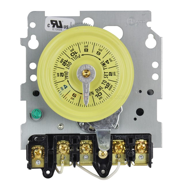
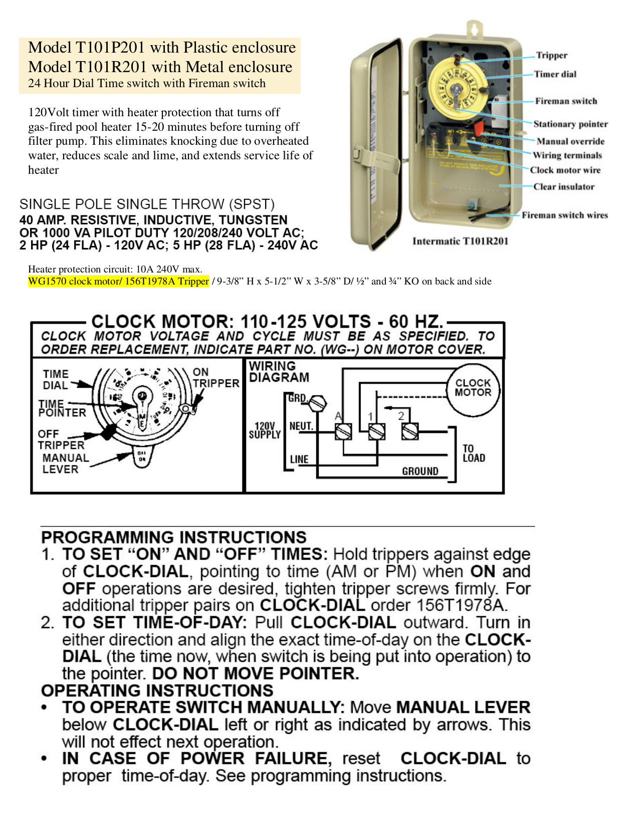
TYPICAL WIRING DIAGRAM CLOCK MOTOR / VOLT 3 WIRE SUPPLY TO LOADS GROUND LINE 2 LINE 1 A 2 4 GR. 1 3 NEUT. The T Series Mechanical Time Switch has proven it can stand the test of time. These dependable time switches can handle electrical loads up to 40 A per .

Intermatic Pool Pump Timer Wiring Diagram
2 Aerian ie AllSync Master Installation & Operation Manual American Time 140 3rd Street South, PO Box 707 Dassel, MN 55325-0707 Phone: 800-328-8996 Fax: 800-789-1882 american-time.com

Intermatic 240v Timer Wiring Diagram | Free Wiring Diagram
Nov 15, 2018 · WIRING. DIAGRAM. V 2 WIRE. AND GROUND. LR UL and align the exact time-of-day on the CLOCK-DIAL (the time now, when. WIRING INSTRUCTIONS: To wire switch follow diagram above. Use solid or of CLOCK-DIAL, pointing to time (AM or PM) when ON and. OFF operations are. Connect the ground wire to the green screw located on the Intermatic timer mechanism.
33 Intermatic Timer Wiring Diagram - Wiring Diagram Database
clock motor: 208-277 volts - 60 hz. clock motor voltage and cycle must be as specified. to order replacement, indicate part no. (wg--) on motor cover. wiring diagram 240 v 2 wire and ground lr3730 document1 10/30/03 1:36 pm page 1
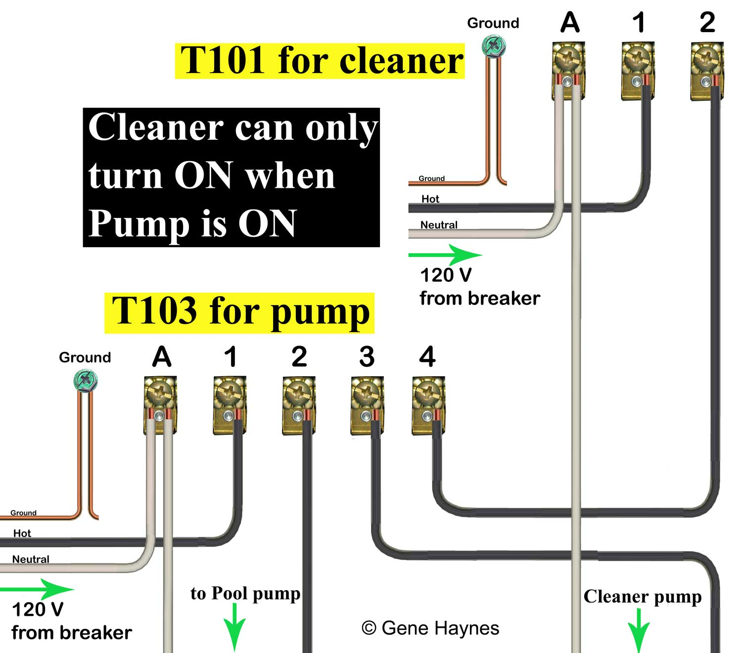
Intermatic T101 Timer Wiring Diagram
Tork Time Clock Wiring Diagram - wiring diagram is a simplified all right pictorial representation of an electrical circuit. It shows the components of the circuit as simplified shapes, and the skill and signal links between the devices.

Staircase Wiring With Timer Diagram Explain (Hindi/Urdu ...
IBM (International Time Recording Co.) Master Clock Wiring. Hello. I purchased a large International Time Recording Co. master clock on ebay a couple of weeks ago. Perhaps some of you saw it. It's one of those big ones installed in a school in 1927 to run the slave clocks and the bell system. Its model number is 13 6 12.

Wiring diagram for timer and tether. | Download Scientific ...
The X terminal would be for.tork time clock wiring diagram - A Novice s Guide to Circuit Diagrams. Not sure how to wire my Tork 1103 timer. An initial take a look at a circuit representation may be confusing, yet if you can read a subway map, you could review schematics. In the wiring diagram above, it shows white neutral wire running to Tork ...

Intermatic Timer T104 Wiring Diagram Download
http://www.sparkyuonline.com In this video i show how to wire a 110 volt time clock that will operate a contactor. The contactor handles the electrical vol...

Single Phase Timer And Contactor Wiring Diagram
Sep 28, 2020 · Intermatic Digital Timer Wiring Diagram – wiring diagram is a simplified satisfactory pictorial representation of an electrical circuit. It shows the components of the circuit as simplified shapes, and the knack and signal links together with the devices.
Tork Time Clock Wiring Diagram
In this video I will go over the Defrost time clock Wiring and Troubleshootinghttps://www.facebook.com/RKETEC/

I have 3 400 watt MH lights 208 volts that I want to have ...
Put the time clock contacts AFTER the photocontrol in series with the red lead. Set the time clock to come on during daylight and off at 3AM. Photocontrols need to be hot all the time. In operation, photocontrol turns on the lights at dusk (time clock is already on) then the time clock turns them off at 3AM. -Hal

Collection Of Paragon Defrost Timer 8145 20 Wiring Diagram ...
The next step in wiring the time switch is to connect the neutral wires. Cut an 8-inch length of white insulated wire as a pigtail, then strip 1/2 inch of insulation from each end. Insert one bare end of the pigtail into the neutral screw terminal on the switch and tighten the screw. This terminal may be marked NEUTRAL, or it may be indicated ...

Intermatic T-101R 120V 40-Amp Timer Switch T101R NEW | eBay

Grasslin Timer Wiring Diagram - 36

Intermatic 240v Timer Wiring Diagram

Astronomical Time Clock Wiring Diagram - Wiring Diagram Schema

Intermatic 3 Circuit Timer Wiring Diagram
Electrical Education | Electricians Training - How to wire ...

Paragon 8145 00 Wiring Diagram Sample

Get Intermatic Timer T104 Wiring Diagram Sample

Intermatic Timer T104R 24 Hour Dial 208V-277V 40-Amp 2 ...

I have 3 400 watt MH lights 208 volts that I want to have ...

Paragon Defrost Timer 8145 20 Wiring Diagram Gallery
26 Swimming Pool Timer Wiring Diagram - Wiring Database 2020
Defiant Digital Timer Wiring Diagram
Intermatic T103 Wiring Diagram Download - Wiring Diagram ...

Geyser Electrical Wiring Diagram

Anly Timer Wiring Diagram

Intermatic Pool Timer Wiring Diagram | Free Wiring Diagram

Intermatic Timer Wiring Diagram T101

Photocell And Timeclock Wiring Diagram - Wiring Diagram ...
Astronomical Time Clock Wiring Diagram - Wiring Diagram Schema
Wiring Diagram For Intermatic Timers

Intermatic R8806p101c Wiring Diagram Collection
Grasslin Pool Timer Wiring Diagram - Wiring Diagram

Intermatic T101 Timer Wiring Diagram - General Wiring Diagram

Paragon Defrost Timer 8145 20 Wiring Diagram Gallery

9 Simple Wiring A Timer Switch Diagram Collections - Tone ...
Astronomical Time Clock Wiring Diagram - Wiring Diagram Schema


Komentar
Posting Komentar