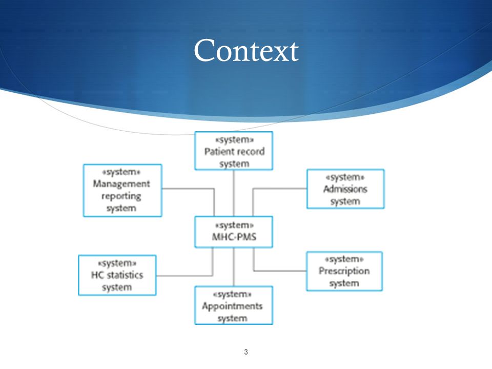
43 context model diagram
The context diagram is used to establish the context and boundaries of the system to be modelled: which things are inside and outside of the system being modelled, and what is the relationship of the system with these external entities. A context diagram, sometimes called a level 0 data-flow diagram, is drawn in order to define and clarify the ... Context Diagram The context diagram of a vision document is a simple diagram that shows the source systems contributing data to a DW/BI system, as well as the major user constituents and downstream information systems that is supports.
Context diagrams are an excellent tool for facilitating brainstorming among those design and analyze them. A context diagram is suitable for noting omissions and blunders in a business plan or project requirements. Hence you can make necessary corrections and adjustments before the project execution and reduce project risks.

Context model diagram
The system context diagram (also known as a level 0 DFD) is the highest level in a data flow diagram and contains only one process, representing the entire system, which establishes the context and boundaries of the system to be modeled. It identifies the flows of information between the system and external entities (i.e. actors). Library Management System - Context Diagram. Use Creately's easy online diagram editor to edit this diagram, collaborate with others and export results to multiple image formats. You can edit this template and create your own diagram. Creately diagrams can be exported and added to Word, PPT (powerpoint), Excel, Visio or any other document. What are the parts of a context diagram? Context diagrams are made up of simple parts: boxes and lines. According to Wikipedia, "Context diagrams can be developed with the use of two types of building blocks: labeled boxes, one in the center representing the system and around it multiple boxes for each external actor, and relationship, labeled lines between the entities and system".[6]
Context model diagram. A system context diagram (SCD) in engineering is a diagram that defines the boundary between the system, or part of a system, and its environment, showing the entities that interact with it. This diagram is a high level view of a system. It is similar to a block diagram . Contents 1 Overview 2 Building blocks 3 Alternatives 4 See also 5 References How to make a context diagram 1 Select the "Data Flow" shape library or choose a template Open the Shape Manager and select the "Data Flow" symbols to start from scratch, or select a template to customize from the template gallery using our context diagram tool. 2 Place your system in the center of your context diagram Context diagram—The topmost diagram in an IDEF0 model. Parent/child diagram—An IDEF0 decomposition hierarchy using parent/child relationships. Node trees—Tree-like structures of nodes rooted at a chosen node and used to represent a full IDEF0 decomposition in a single diagram. Create a context diagram Open Visio. A Context Diagram shows the system being modeled in relationship to external systems. It could show data flowing in from and out to external systems, modeled by a data flow diagram (not part of UML). It could show behavioral interactions between the system and external "actors", modeled by a UML use case diagram.
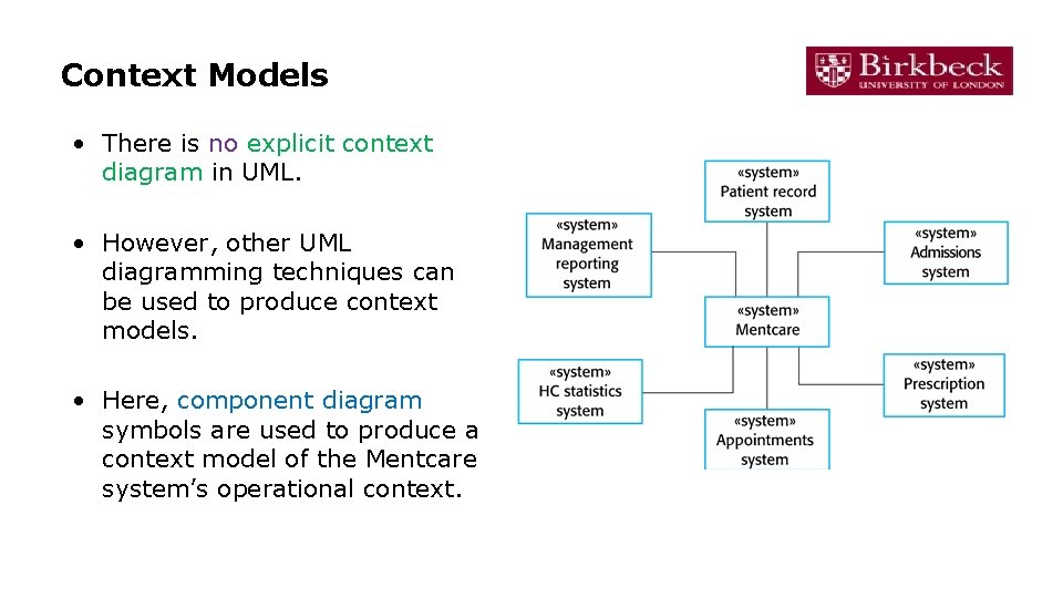
Domain Model Design Tools. A simple tool to generate Context Map and Domain Model with Java annotation. Introduction. As an architect, I found myself wasted a lot of time drawing and updating diagrams. DSL like plantuml works good enough for simple diagrams however. it is difficult to control the layout of the diagram. UML diagram types •Activity diagrams, which show the activities involved in a ... model the interactions between the actors and the ... • Context models show how a system that is being modeled is positioned in an environment with other systems and processes. A context diagram is a graphical representation of a system which must only use one process to represent the entire system and deliberately does not go into defining all the processes so as to prevent people getting bogged down in complex details at an early stage. There are only three symbols used in a context diagram: Transition Diagram. A transition diagram or state transition diagram is a directed graph which can be constructed as follows: There is a node for each state in Q, which is represented by the circle. There is a directed edge from node q to node p labeled a if δ(q, a) = p. In the start state, there is an arrow with no source.
A sequence diagram is a good way to visualize and validate various runtime scenarios. These can help to predict how a system will behave and to discover responsibilities a class may need to have in the process of modeling a new system. Sequence Diagram Tutorial. Start with one of SmartDraw's included sequence diagram templates. How to Draw Context Level DFD? To create new DFD, select Diagram > New from the toolbar. In the New Diagram window, select Data Flow Diagram and click Next. Enter Context as diagram name and click OK to confirm. We'll now draw the first process. From the Diagram Toolbar, drag Process onto the diagram. Name the new process System. System Context Diagram: • A System Context Diagram (SCD) in software engineering and systems engineering is a diagram that defines the boundary between the system, or part of a system, and its environment, showing the entities that interact with it. • This diagram is a high level view of a system. 8. Context Diagram. The venerable context diagram dates from the structured analysis revolution of the 1970s. Despite its antiquity, the context diagram remains a useful way to depict the environment in which a software system exists. Figure 1 illustrates a partial context diagram for a hypothetical corporate cafeteria ordering system.
What is a Data Flow Diagram | Lucidchart
the school context model: how school environments shape students opportunities to learn table of contents introduction: schools and student learning the evolution of learning environment research context matters school climate process and context how school context shapes core processes of teaching and learning

Trajectory Context Model represented in UML notation ...
Context Diagram Software The Simplest Way to Create Context Diagrams Online Start Drawing Now Over 6 Million people and 1000s of teams already use Creately Draw context diagrams with minimal effort Visualize systems and their surrounding environment effortlessly with Creately.

UML context model for the case study (A) and our context ...
What is a context diagram. A model that shows how your product interacts with outside people, organizations, and/or systems. The context diagram helps you to identify the interfaces you need to account for, helps you to identify scope, identify potential stakeholders, and build a better understanding of the context in which you are working.

Context Model - an overview | ScienceDirect Topics
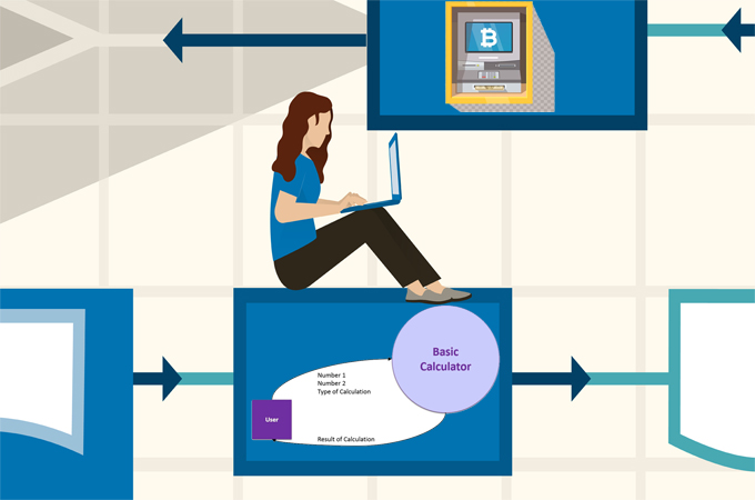
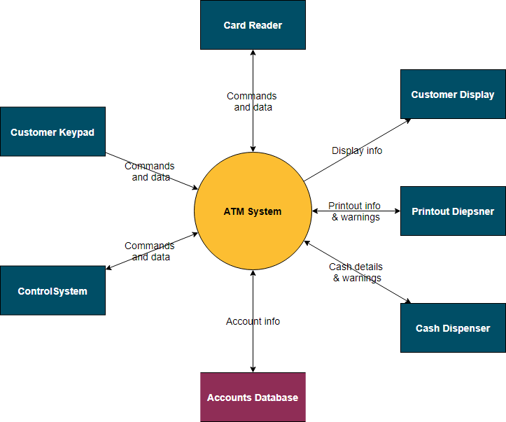
ATM System - Context Model Try Visual Paradigm Online (VP Online). It is an online drawing software with support to System Context Diagram and other diagrams such as BPD, ERD UML, flowchart and organization chart. You can easily draw System Context Diagram through the simple, intuitive UML editor. Edit this Template

System Context Diagram: Description & Examples Video
Independent Events Venn Diagram. Let us proof the condition of independent events using a Venn diagram. Theorem: If X and Y are independent events, then the events X and Y’ are also independent. Proof: The events A and B are independent, so, P(X ∩ Y) = P(X) P(Y). Let us draw a Venn diagram for this condition:
Chapter 5 Process Modeling SYSTEMS ANALYSIS AND DESIGN
A System Context diagram is a good starting point for diagramming and documenting a software system, allowing you to step back and see the big picture. Draw a diagram showing your system as a box in the centre, surrounded by its users and the other systems that it interacts with.
What is A Context Diagram with Examples | EdrawMax Online
6) Semantic Data Model: A semantic data model in software engineering is a technique to define the meaning of data within the context of its inter-relationships with other data. A semantic data model is an abstraction which defines how the stored symbols relate to real world. A semantic data model is sometimes called a conceptual data model.
What is context diagram? - Quora
Model Causal diagram. A causal diagram is a directed graph that displays causal relationships between variables in a causal model. A ... In the context of causal models, potential outcomes are interpreted causally, rather than statistically. The first law of causal inference states that the potential outcome can be computed by modifying causal model M (by deleting arrows into X) …

Context Model - an overview | ScienceDirect Topics
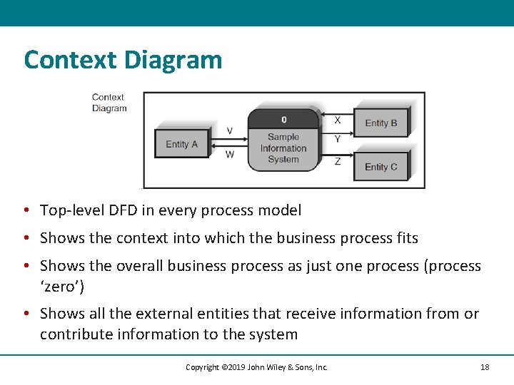
The Context Diagram shows the system under consideration as a single high-level process and then shows the relationship that the system has with other external entities (systems, organizational groups, external data stores, etc.). Another name for a Context Diagram is a Context-Level Data-Flow Diagram or a Level-0 Data Flow Diagram.
What is A Context Diagram with Examples | EdrawMax Online
Choose the context of an interaction: system, subsystem, use case, and operation. Think through alternative situations that may be involved. Implementation of a collaboration diagram at an instance level, if needed. A specification level diagram may be made in the instance level sequence diagram for summarizing alternative situations.
![Organisational Context Model [Level 0] : A Practical Guide To ...](https://deliveringresults.leeds.ac.uk/wp-content/uploads/sites/8/2019/05/doc-level-0.png)
Organisational Context Model [Level 0] : A Practical Guide To ...
This is a context level data flow diagram of a library (book) information system. The example illustrates the flow of information between the system of interest (Book information system) and its external entities (the Librarian and the File System). It provides an understanding of the main type of data that evoke actions in the Book information ...

Block Diagram of Context-aware System. | Download Scientific ...
25.11.2009 · A context map is a tool for today, and today the problem is still open, so we leave the caution sign in the diagram. Don't be fooled by the colors and shadows: I tried to make the context map look ...
Software Engineering I Session 4 Software Modelling Recap
Drawing a context diagram helps you to understand how a system interacts with other systems, business units, and key personnel. In addition, you can use it to help define the scope of a system's...

Context Model - an overview | ScienceDirect Topics
A context diagram is one of the first diagrams you will start creating when you begin looking at software design and development. It is a diagram which will help you define what the problem is that your software is going to solve. It does this by showing who your system will interact with and what data is incolved.
Chapter 5 System Modeling 1. Context Model ï“ Shows context ...
C4 system context diagram. This top-level diagram is also the most abstract. C4 system context diagrams show the big picture, how users interact with your software system as a whole, and how your software fits together with other existing software systems.

What Comes Before The Use Case Model?
Context diagrams are visual tools that depict the scope of the product showing the business system and how it relates and interacts with the other systems as well. It is a good example of a project management scope model. It shows the inputs to the system, the main players that provide the input as well as the output of the system and the actors receiving them.

Introduction to Context Diagrams > Business Analyst Community ...
In these relationships the "many" or child documents always appear with or are viewed in the context of the "one" or parent documents. See Model One-to-Many Relationships with Embedded Documents . In general, embedding provides better performance for read operations, as well as the ability to request and retrieve related data in a single ...
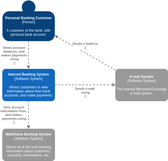
C4 Model System Context Diagram for Internet Banking System ...
A context diagram is a visual representation of the relationship between data and business processes. This diagram has 3 main components which include external entities, system processes, and data flows. It provides the factors and events you need to consider when developing a system.
What is A System Context Diagram with Explanation Examples
What are the parts of a context diagram? Context diagrams are made up of simple parts: boxes and lines. According to Wikipedia, "Context diagrams can be developed with the use of two types of building blocks: labeled boxes, one in the center representing the system and around it multiple boxes for each external actor, and relationship, labeled lines between the entities and system".[6]

Putting Systems Analysis “Into Context†using the Context Diagram
Library Management System - Context Diagram. Use Creately's easy online diagram editor to edit this diagram, collaborate with others and export results to multiple image formats. You can edit this template and create your own diagram. Creately diagrams can be exported and added to Word, PPT (powerpoint), Excel, Visio or any other document.

Project context diagrams
The system context diagram (also known as a level 0 DFD) is the highest level in a data flow diagram and contains only one process, representing the entire system, which establishes the context and boundaries of the system to be modeled. It identifies the flows of information between the system and external entities (i.e. actors).
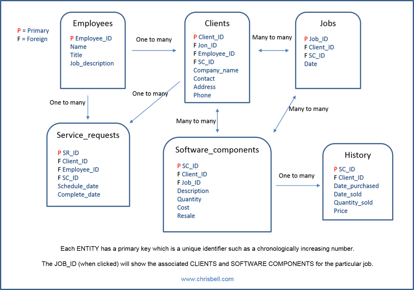
Context Based ERD Model With Attributes | Chris Bell
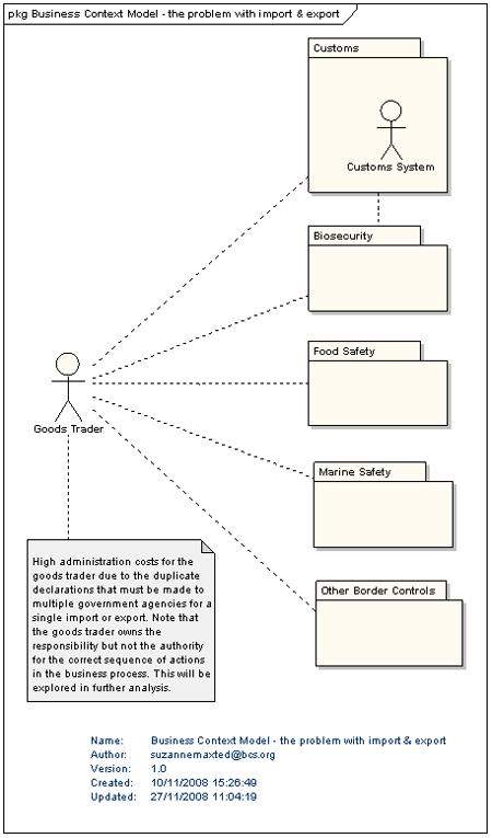
The Business Context Model; As Good as it Gets - Business ...
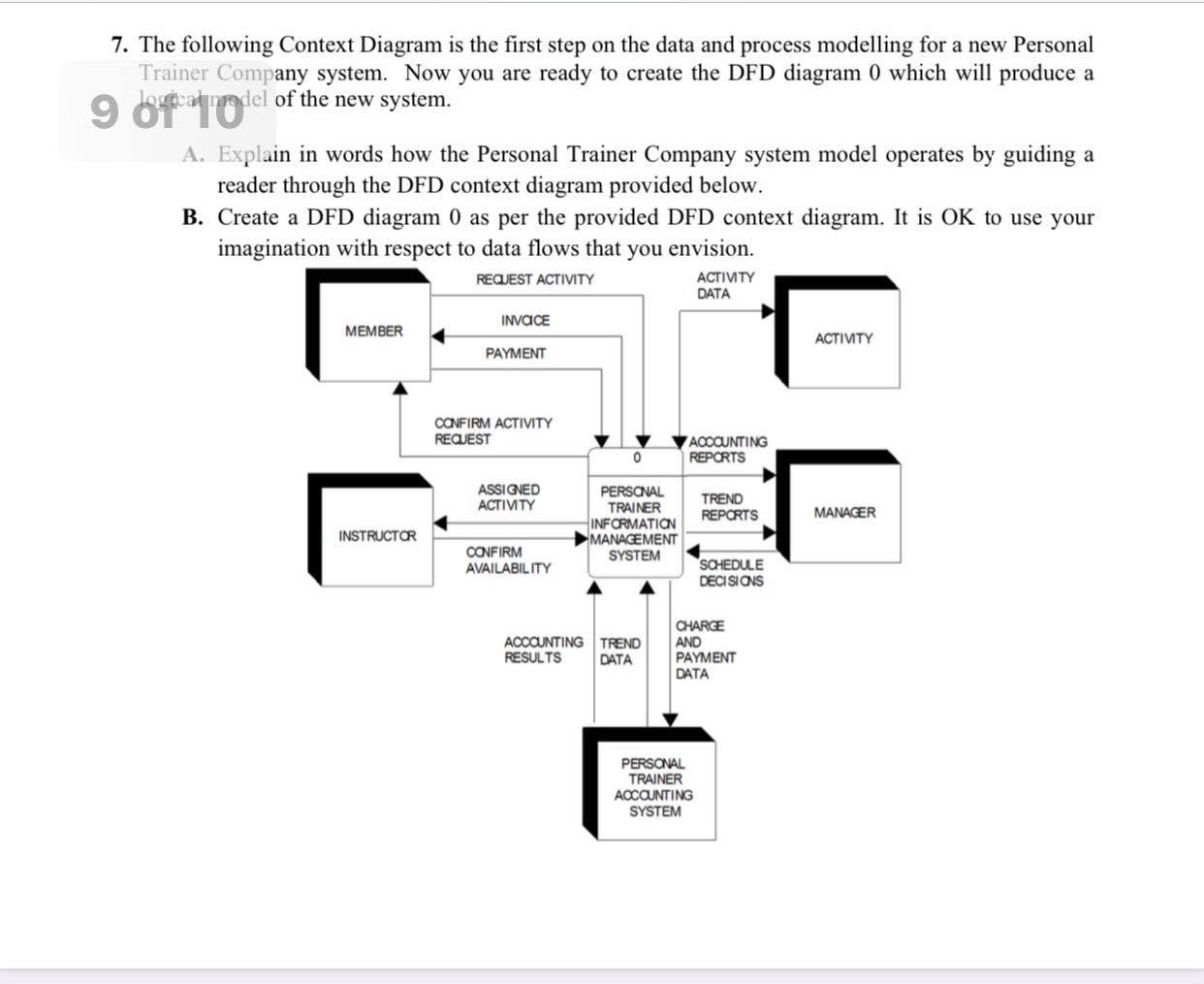
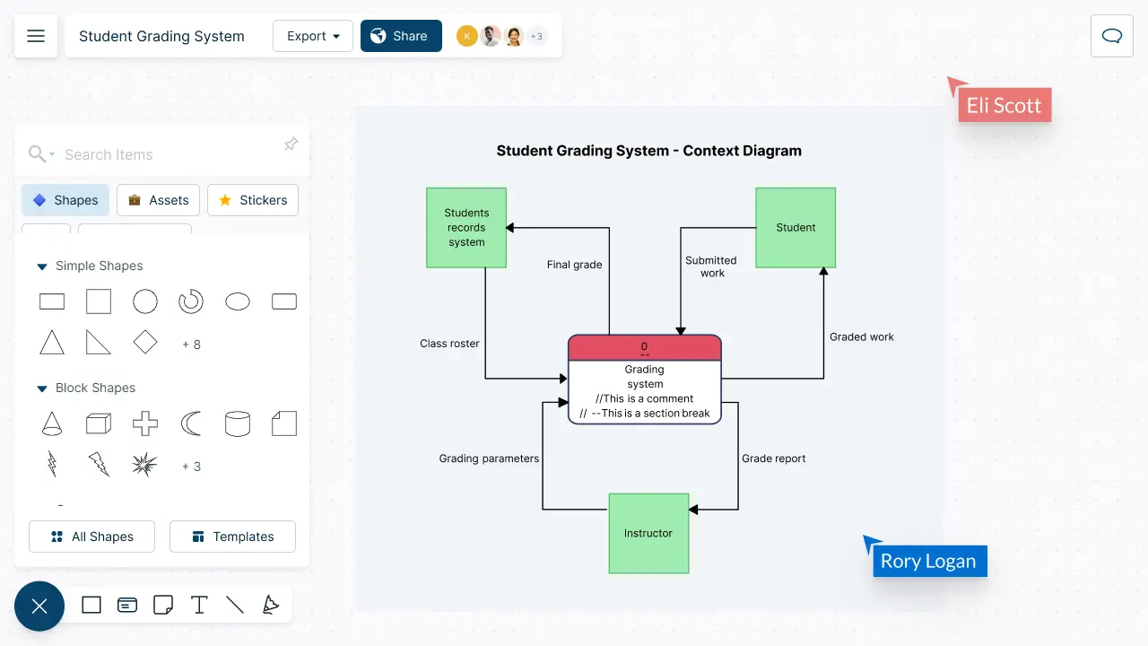
7. The following Context Diagram is the first step on | Chegg.com
Blog - Create C4 models and diagrams

What is a Data Flow Diagram | Lucidchart
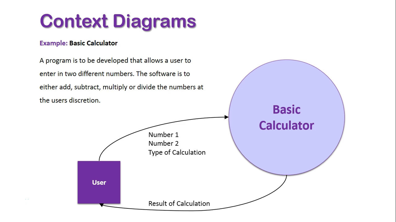
Context Diagrams Overview
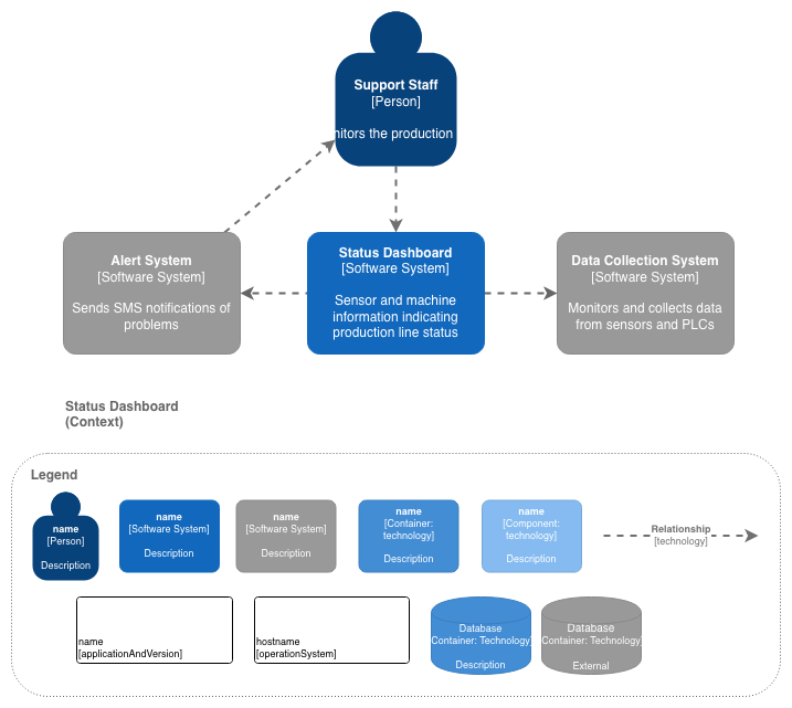
Design Workshop – Week 3 – System Context and Component ...
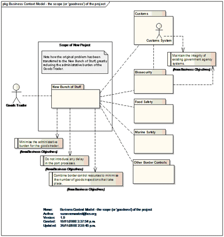
The Business Context Model; As Good as it Gets - Business ...
Context model

Example context model as ER diagram. | Download Scientific ...

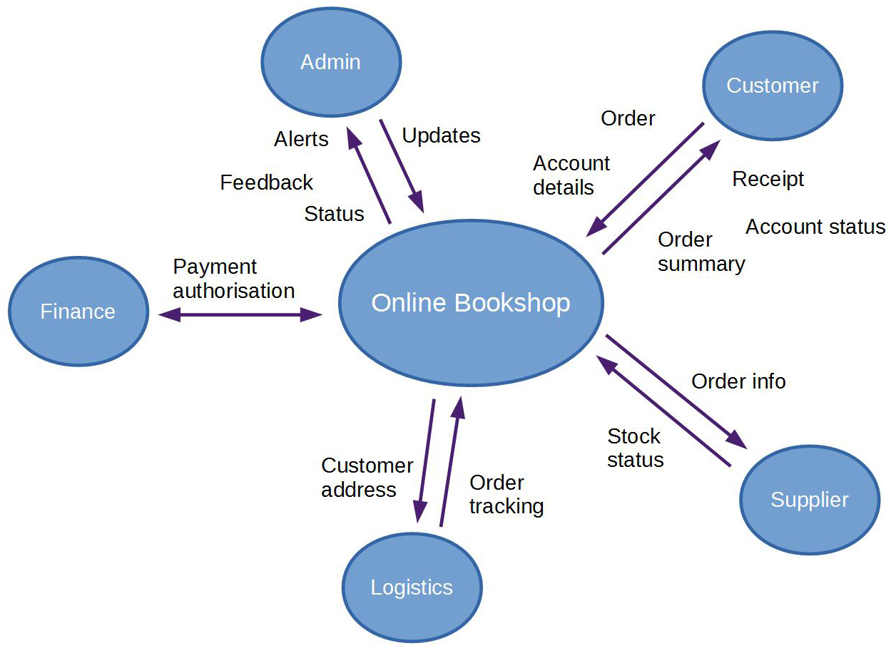
Part of Context Diagram or Context Model of the Bookstore ...
Context Diagram Software | Context Diagram Maker | Creately

System context diagram Entity–relationship model Context ...
What is A Context Diagram with Examples | EdrawMax Online
What is A Context Diagram with Examples | EdrawMax Online
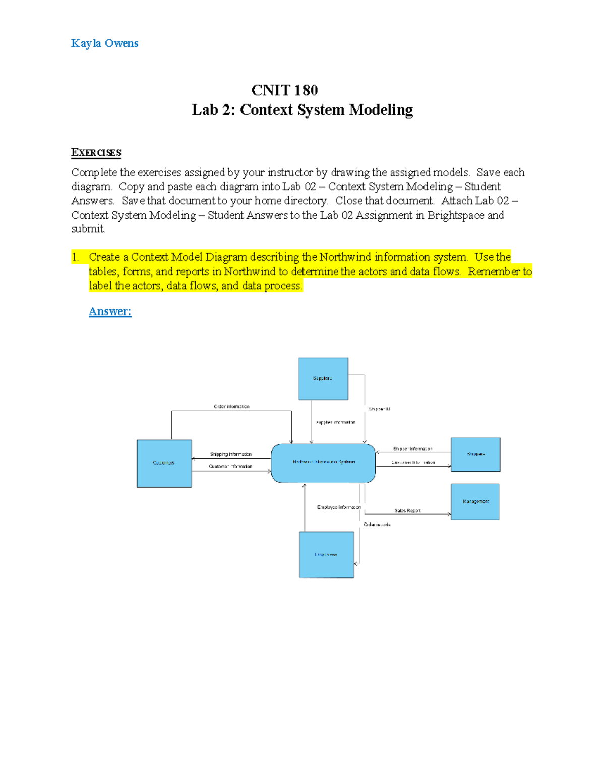
Lab 02 - Context System Modeling - Student Answers - CNIT ...

File:Hatley-Pirbhai System Context Diagram.png - Wikimedia ...
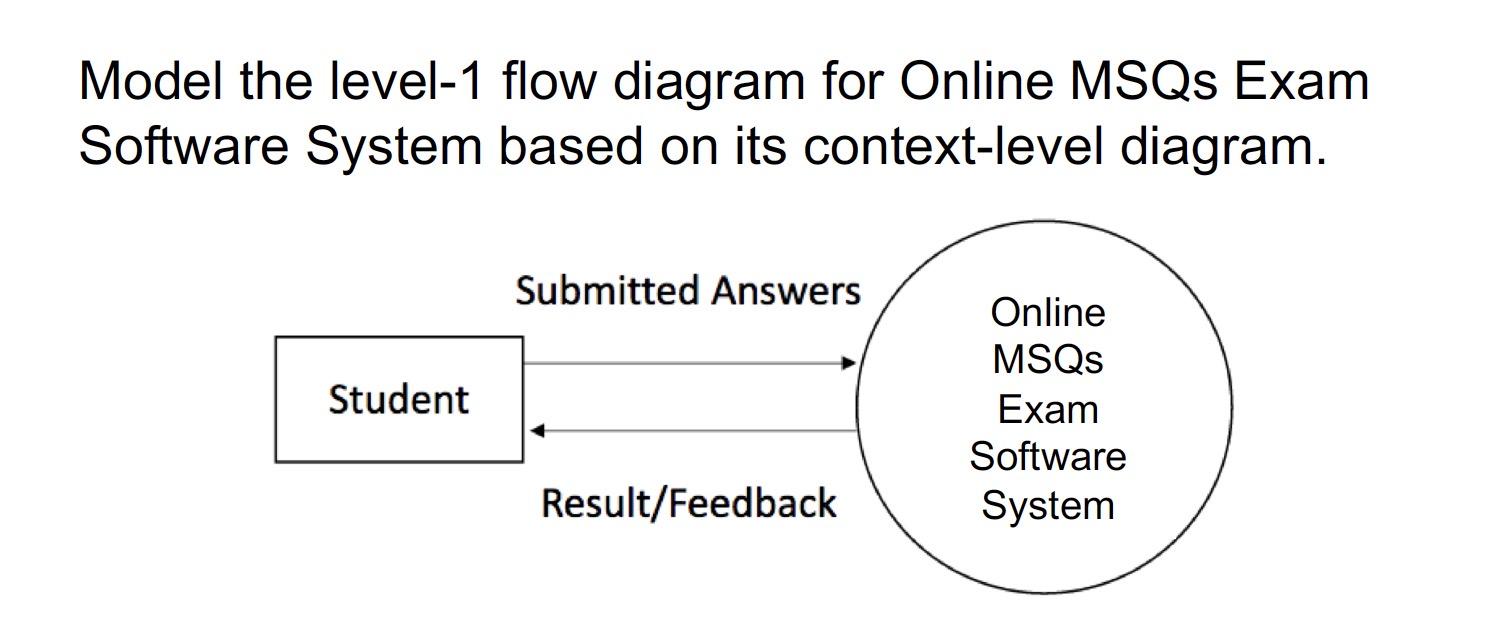
Solved Model the level-1 flow diagram for Online MSQs Exam ...

A Context Model in 5 Minutes - Why Change

Context Diagram In A Nutshell - FourWeekMBA

Context diagram for the proposed model. | Download Scientific ...
Context diagrams


Komentar
Posting Komentar