40 state transition diagram maker
Reading Time: 6 min State diagrams quickly show which states lead to each other, and what triggers a change of state. They are easy to create with draw.io and its built-in UML shape library. In this diagram, there are three possible states 1, 2, and 3, and the arrows from each state to other states show the transition probabilities p i j. When there is no arrow from state i to state j, it means that p i j = 0 . Figure 11.7 - A state transition diagram. Example. Consider the Markov chain shown in Figure 11.7.
State Transition Diagram Example. Use Creately’s easy online diagram editor to edit this diagram, collaborate with others and export results to multiple image formats. You can edit this template and create your own diagram. Creately diagrams can be exported and added to Word, PPT (powerpoint), Excel, Visio or any other document.

State transition diagram maker
State diagram. The state diagram is the pictorial representation of the behavior of sequential circuits. It clearly shows the transition of states from the present state to the next state and output for a corresponding input. Infinite canvas to draw large, complex state machine diagrams with minimal effort.. Smart shapes and connectors, shape search, and easy styling options to quickly and easily create all types of UML diagrams.. Simple to use drag-drop tools and Plus Create to quickly visualize any process, flow, system, or idea.. Link to external documents and open them within the canvas for detailed information. A state diagram is a graphic representation of a state machine. It shows a behavioral model consisting of states, transitions, and actions, as well as the events that affect these. It's also one of the 14 Unified Modeling Languages (UML) used for specifying, visualizing, constructing, and documenting software systems.
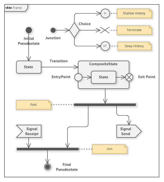
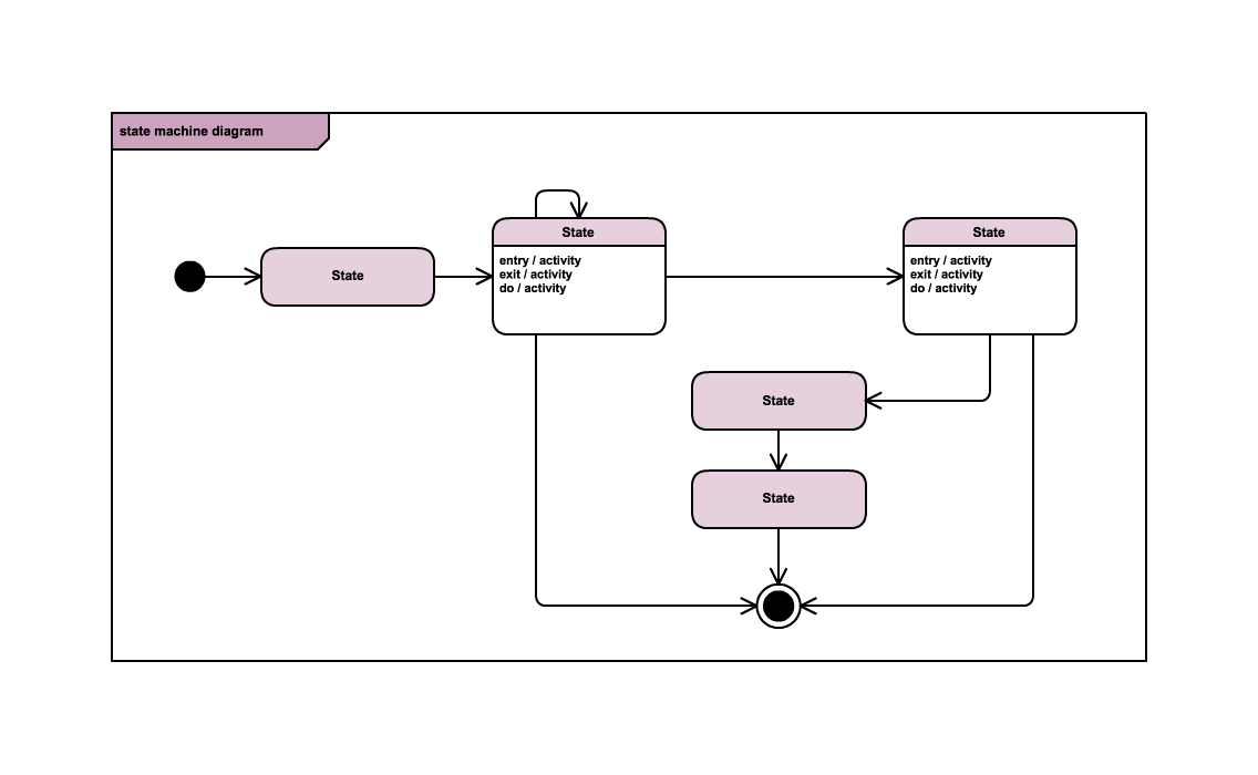
State transition diagram maker. Initial and Final States. The initial state of a state machine diagram, known as an initial pseudo-state, is indicated with a solid circle. A transition from this state will show the first real state The final state of a state machine diagram is shown as concentric circles. An open loop state machine represents an object that may terminate before the system terminates, while a closed loop ... UML state machine's goal is to overcome the main limitations of traditional finite-state machines while retaining their main benefits. Draw State Transition ... What is a State Machine Diagram? State Diagram are used to capture the behavior of a software system. UML State machine diagrams can be used to model the behavior of a class, a subsystem, a package, or even an entire system. It is also called a Statechart or State Transition diagram. What is a Statechart Diagram? Finite State Machines • Design methodology for sequential logic-- identify distinct states-- create state transition diagram-- choose state encoding-- write combinational Verilog for next-state logic-- write combinational Verilog for output signals • Lots of examples 6.111 Fall 2017 Lecture 6 1
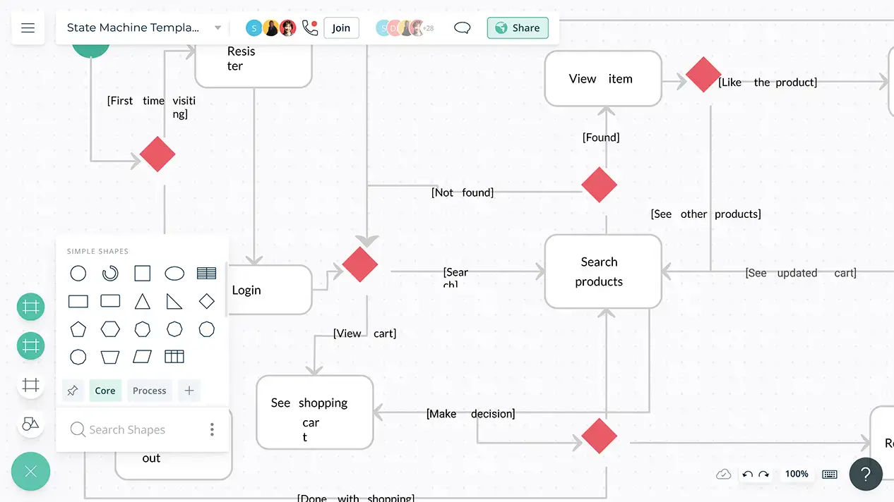
Free editor to create online diagrams. Use our diagram editor to make Flowcharts, UML diagrams, ER diagrams, Network Diagrams, Mockups, floorplans and many more. Open and save your projects and export to Image or PDF. the HTML5
Looking for a transition tree maker? VP Online helps you create transition trees quickly and easily. The transition trees tool comes with all the symbols you need to construct your transition tree. Combining with the drag-and-drop editor and powerful feature set, you can create professional transition trees in a snap. In this two state diagram, the probability of transitioning from any state to any other state is 0.5. Of course, real modelers don't always draw out Markov chain diagrams. Instead they use a "transition matrix" to tally the transition probabilities. Every state in the state space is included once as a row and again as a column, and each cell in ... VP Online features a powerful UML diagram tool that lets you create state machine diagram and other UML diagrams easily and quickly. You can construct your diagrams with drag and drop, save your work in cloud workspace, output and share your design via numerous formats such as PNG, JPG, SVG, PDF, etc. Followings are some of the free UML state machine diagram templates we provide to help you get a quick start. A state diagram, sometimes known as a state machine diagram, is a type of behavioral diagram in the Unified Modeling Language (UML) that shows transitions between various objects. Using our collaborative UML diagram software, build your own state machine diagram with a free Lucidchart account today! 4 minute read
State Diagrams - Everything to Know about State Charts
TCP/IP State Transition Diagram (RFC793) Gordon McKinney (23 Feb 2002) A connection progresses through a series of states during its lifetime. The states are: LISTEN, SYN-SENT, SYN-RECEIVED, ESTABLISHED, FIN-WAIT-1, FIN-WAIT-2, CLOSE-WAIT, CLOSING, LAST-ACK, TIME-WAIT, and the fictional state CLOSED.
How to Draw a State Machine Diagram in UML?
Description. This Booch diagram shows states and state transitions. Drawing Instructions. If you haven't already done so, first download the free trialversion of RFFlow. It will allow you to open any chart and make modifications. Once RFFlow is installed, you can open the above chart in RFFlow by clicking on state_transition.flo.

State diagram - Wikipedia
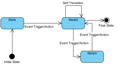
State-Transition Diagrams State-transition diagrams describe all of the states that an object can have, the events under which an object changes state (transitions), the conditions that must be fulfilled before the transition will occur (guards), and the activities undertaken during the life of an object (actions).
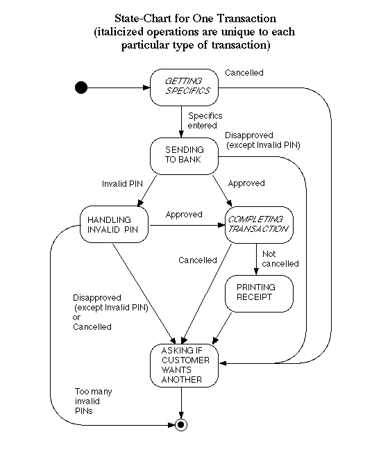
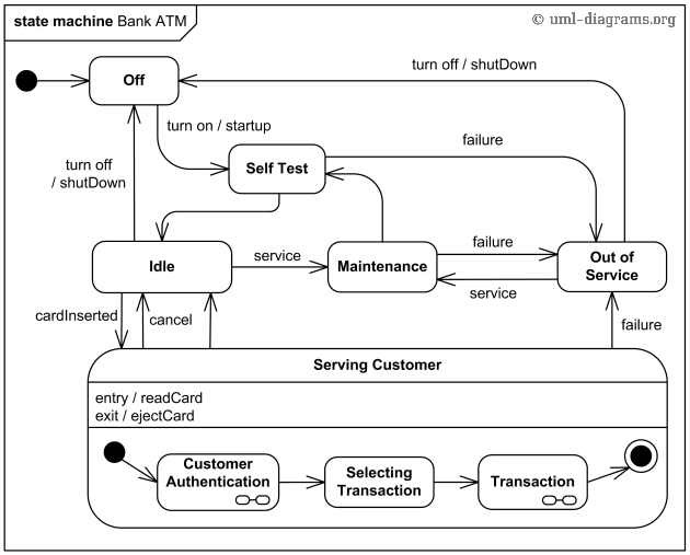
State Charts for Example ATM System
State transition diagrams have been used right from the beginning in object-oriented modeling. The basic idea is to define a machine that has a number of states (hence the term finite state machine). The machine receives events from the outside world, and each event can cause the machine to transition from one state to another.
Objects Use Cases Actors State Transition Diagrams - State ...
State Transition Tables in Stateflow. A state transition table is an alternative way of expressing sequential modal logic. Instead of drawing states and transitions graphically in a Stateflow ® chart, use state transition tables to express the modal logic in tabular format. State transition tables are supported only as blocks in a Simulink ® model.
What is a State Diagram? - Smartpedia - t2informatik
DFA - Simulator. Console: Press Add state button to Add a new node in the diagram and drag the node to custom positions. Q0. Add a State Transition. ×. From. Input. To State. Cancel.

State Diagram - MATLAB & Simulink
The design process begins by creating the state transition diagram (Figure 5.73) and the state transition table. There are five distinct states, so three D-type flip-flops are used (where n = 3, giving 2 n = 8 possible states, although only five states are used).

State Diagram - an overview | ScienceDirect Topics
In the Search box, type UML state machine. Select the UML State Machine diagram. In the dialog box, select the either Metric Units or US Units. Select Create. The diagram opens. You should see the Shapes window next to the diagram. If you don’t see it, go to View > Task Panes and make sure that Shapes is selected.
UML State Machine Diagram Tutorial - Software Ideas Modeler
UMLet is a free open source state diagram maker software for Windows. Using this freeware, you can quickly create state diagrams and variants of UML diagrams. This software also comes with a useful multi-tab interface that enables you to work on multiple state diagrams simultaneously. Plus, examples for all types UML diagrams are also present it.
UML state diagrams with draw.io - draw.io
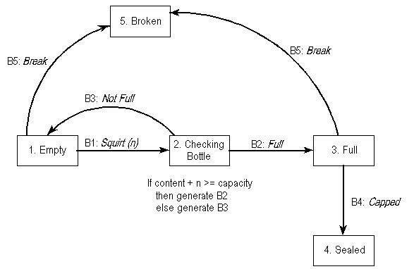
In Software Engineering, State Transition Testing Technique is helpful where you need to test different system transitions. Two main ways to represent or design state transition, State transition diagram, and State transition table. In state transition diagram the states are shown in boxed texts, and the transition is represented by arrows.
State Chart Templates | Editable Online or Download for Free ...
Transition — A state machine Diagram (or start diagram, also called state chart of state transition diagram) is a behavior which specifies the sequence of ...

State Transition Diagram - an overview | ScienceDirect Topics
State Transition diagram can be used when a software tester is testing the system for a finite set of input values. When the software tester focus is to understand the behavior of the object. When the software tester focus is to test the sequence of events that may occur in the system under test. Frequently Asked Questions (FAQ)
UML State Machine Diagrams - Overview of Graphical Notation
Release it, it stays on. Push the button a second time, and the bulb turns off. Release the button, and it stays off. This "enhanced" light bulb state diagram is shown below. The states are as follows: STATE 1 -- The reset state has the bulb turned off and waiting for the button to be pushed to turn it on.
UML - Statechart Diagrams
A state diagram is a graphic representation of a state machine. It shows a behavioral model consisting of states, transitions, and actions, as well as the events that affect these. It's also one of the 14 Unified Modeling Languages (UML) used for specifying, visualizing, constructing, and documenting software systems.

State Machine Diagram - UML 2 Tutorial | Sparx Systems
Infinite canvas to draw large, complex state machine diagrams with minimal effort.. Smart shapes and connectors, shape search, and easy styling options to quickly and easily create all types of UML diagrams.. Simple to use drag-drop tools and Plus Create to quickly visualize any process, flow, system, or idea.. Link to external documents and open them within the canvas for detailed information.

12. Using State Transition Diagrams - Software Requirements ...
State diagram. The state diagram is the pictorial representation of the behavior of sequential circuits. It clearly shows the transition of states from the present state to the next state and output for a corresponding input.
State Chart Templates | Editable Online or Download for Free ...

State Transition Diagram - an overview | ScienceDirect Topics

State Transition Diagram
A simple guide to drawing your first state diagram — with ...

Online State Machine Diagram Tool
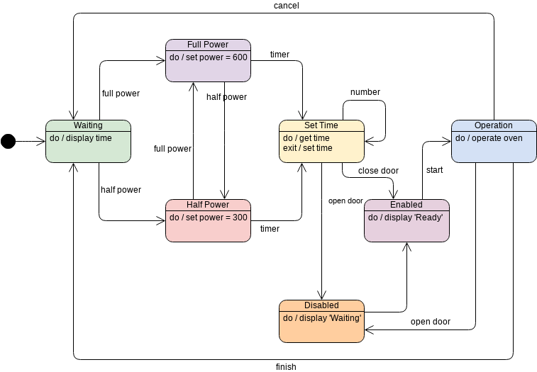
Oven | State Machine Diagram Template

State Transition Testing Technique and State Transition ...

State Transition Diagram - an overview | ScienceDirect Topics
Hierarchical State Machine

UML state machine - Wikipedia

UML state diagrams with draw.io - draw.io

UML 2 State Machine Diagrams: An Agile Introduction
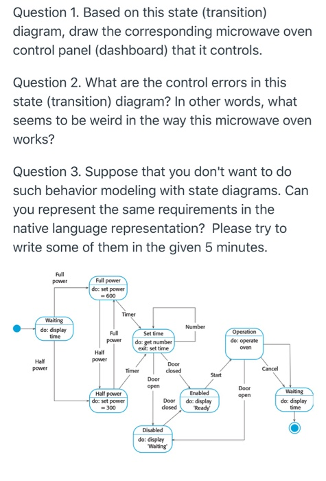
Question 1. Based on this state (transition) diagram, | Chegg.com
State transition diagram - Software Testing Class

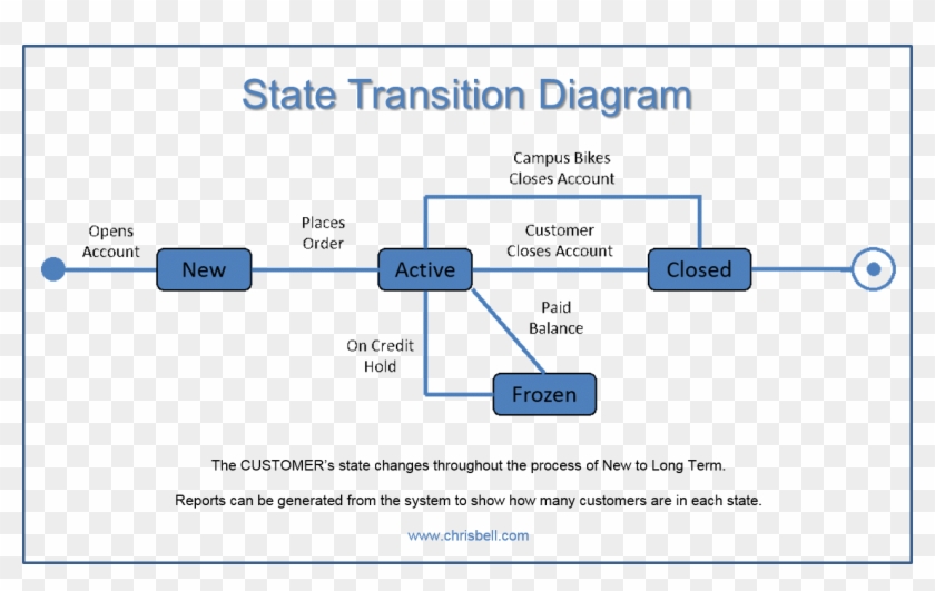
3 Reasons to Use State Models to Derive Software Requirements ...
State Machine Diagram in UML | What is Statechart Diagram?
Unified Modeling Language (UML) | State Diagrams - GeeksforGeeks
State Transition Diagrams

Software engineering: State Transition Diagram
State Diagram Explained | EdrawMax Online
State Transition Diagrams
State Diagram Maker | State Machine Diagram Tool | Creately
A simple guide to drawing your first state diagram — with ...

12. Using State Transition Diagrams - Software Requirements ...


Komentar
Posting Komentar