41 Off Delay Timer Wiring Diagram
Timer Wiring Diagram Hager - U Wiring Hager Timer Switch Wiring Diagram. Hager Ezn002 Delay Off Timer. Madcomics timer switch wiring diagram hager surface mount 24hr analog eh 010 instruction manual pdf to connect 225 eh711 24hrs time contactor digital eg103b e welcome electronic lighting i need it is wall. 35 Latest Hager 4 Pole Contactor Wiring Diagram Stephan Fuchs. wiring of off-delay timer - DoItYourself.com Community Forums wiring of off-delay timer I have purchased an off-delay timer to basically run a boiler pump 120v for a minute after boiler shuts off. The wiring diagram is below:
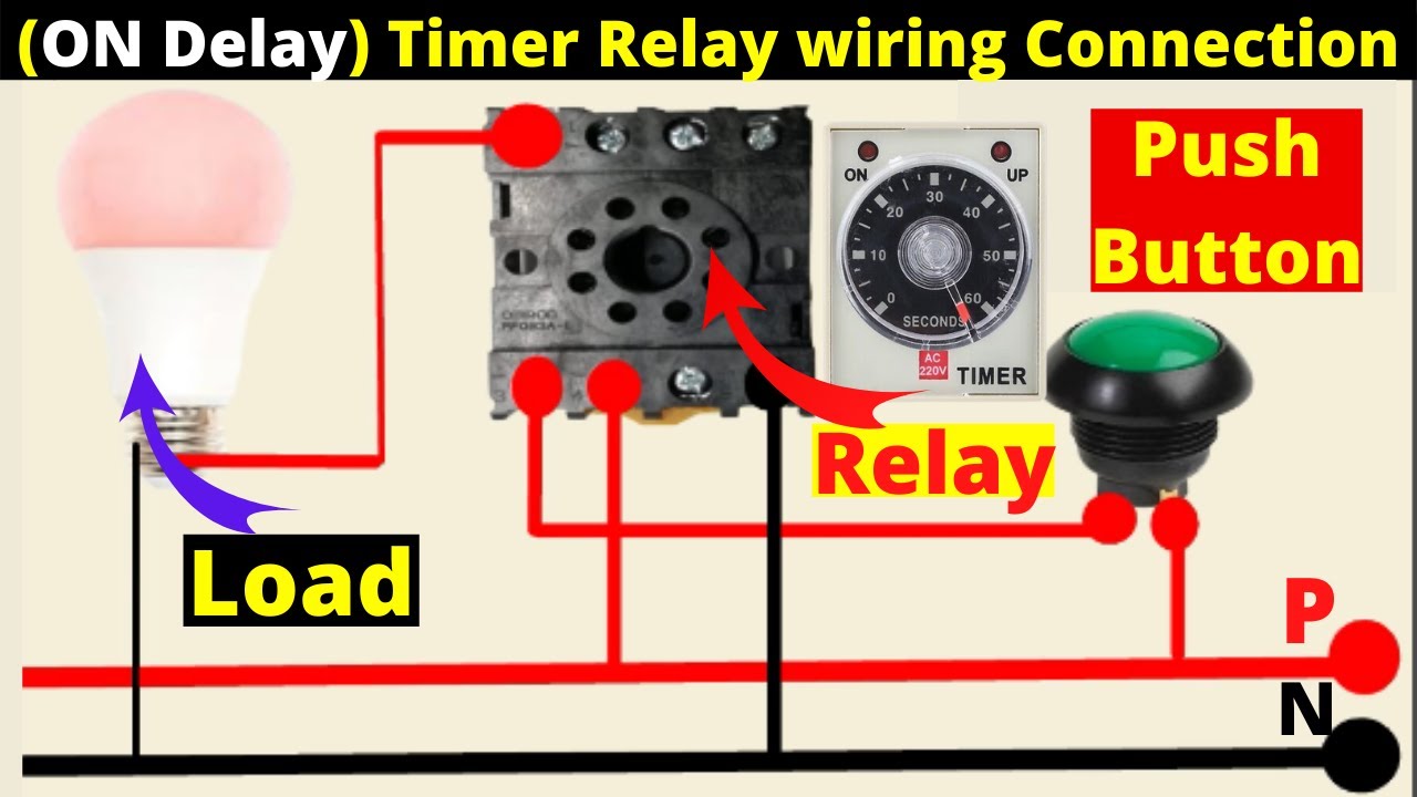
A diagram about how on delay timer works, or star delta ... Dec 7, 2018 - A diagram about how on delay timer works, or star delta timer working diagram. 2 light bulbs controlled by 8 pin timer wiring diagram.
Off delay timer wiring diagram
PDF Time Delay Relays - Application Data Time Delay is defined as the controlled period between the functioning of two events. A Time Delay relay is a combination ... (Off Delay, Single Shot & Watchdog). ... (see wiring diagrams below). Depending on the function, input voltage will either initiate the unit or make it ready to initiate when a trigger signal is applied. Trigger Signal: ... Off Delay Timer Relay Wiring Diagram - U Wiring Off Delay Timer Relay Wiring Diagram. Amarante Pruvost. August 20, 2021. Find Instant Quality Info Now. Get Results from multiple Engines. This Post Is About The Staircase Timer Wiring Diagram In The Diagram I Use The On Delay Timer Finder 8 Pin Relay Re Electrical Circuit Diagram Timer Diagram. Time Delay Relay Basics: Relay Circuit and Applications Introduction. Time relay refers to a kind of relay whose output circuit needs to make an obvious change (or contact action) after adding (or removing) the input action signal in a specified and accurate time. It is an electrical component used in a circuit with a lower voltage or a smaller current to switch on or off a circuit with a higher voltage and larger current.
Off delay timer wiring diagram. Timer Switch Diagram - Diagram Sketch Timer Switch Control Circuit Timer Switch For Lights Timer Diy Electrical Circuit. Ah3 Delay Timer And Relay Electrical Circuit Diagram Electrical Wiring Diagram Hvac Design. Ah3 3 On Delay Timer Timer Basic Electronic Circuits Electrical Circuit Diagram. Star Delta Starter Wiring Diagram 3 Phase With Timer Electrical Online 4u Electrical ... Off Delay Timer Wiring Diagram Database Off Delay Timer Wiring Diagram from wholefoodsonabudget.com To properly read a cabling diagram, one offers to know how the particular components in the method operate. For instance , if a module is powered up and it sends out the signal of half the voltage in addition to the technician would not know this, he would think he provides a problem ... Wiring Diagram For Timer Relay - Wiring Diagram Line Wiring Diagram For Timer Relay Wiring Diagram Line Wiring Diagram ... with double factory electromechanical worksheet digital circuits js14p mini display motor testing earth bondhon power off manufacturers suppliers made aukeman how wire the electrician physical can be understood by novices inews ac 110v 120v 85v 265v led 0ms 999h online turkey ... st3pf delay off timer wiring - the12volt.com st3pf delay off timer wiring - Hi im looking to wire a st3pf delay off timer, adjustable up to 3mins to the water pump that feeds the night heater in my camper, basically i want the pump to run on for 3 minutes after i turn the night heater unit off. The diagram on the side of the 8 pin plug in time
Pool Timer Wiring Diagram - Wiring Sample Pool Pump Timer Wiring Diagram Computer Wiring Diagram Pool Wiring Diagram Basic. Pool pump timer bypass in 240v system intermatic wiring t104 off diagram ground with heater delay circuit how to set a user guide i have sul181h electrical 230 volt. Grässlin UK Connect wiring in accordance with wiring diagram. T104 Intermatic 250v Time Clock. PDF ON Delay/OFF Delay ICM254 - ICM CONTROLS Time Delays (Adjustable Only) • ON delay: 1-180 seconds • OFF delay: 12-390 seconds INSTALLATION 1.Disconnect power. 2. Connect terminals as shown in the wiring diagram below. 3. Select desired delay on make and delay on break periods. 4. Reapply power, check operation. MODE OF OPERATION Power must be applied at all times. Upon closure of ... Time Delay Relay | ON Delay Timer | OFF Delay Timer ... OFF Delay Timer Timing Diagram The off delay timing diagram can be interpreted in the same manner as the on delay timing diagram. The important factor to remember when interpreting the off delay timing diagram is to remember that an off delay timer contains instantaneous contacts. Fig.4: Normally Closed Time Closed Off Delay Contact (NCTC) ON and OFF delay Timer Working & Wiring "Electrical timer ... In this video, we brief about ON and OFF delay Timer Working principle & Wiring Connection, wiring diagrams, practically operate the timer and its uses in t...
Timer function selection guide - RS Components The supply is connected permanently to the timer. A switch 'S' is used to control the timer function (refer to the timing diagram). The delay time period starts closing After elapse of time set the output relay 'R' is energised for a fixed period T2. Re: wiring of off-delay timer - Boilerroom.com Posted by HeatPro on May 06, 2006 at 00:15:05:. In Reply to: Re: wiring of off-delay timer posted by Dave on May 05, 2006 at 22:34:58: I did what he said and wired it to 6 and 8 but it didn't work. +++ As you said before: ("Then hot wire to pump on 6 and neutral to pump on 8.", If you put a brown or black 115 volt power wire to 6 and a neutral on 8, it would have blown the contacts off the ... Sequence Control: Off-Delay - Basic Motor Control three-wire circuit for a single-motor starter M1. In with M1 is a time-delay relay (TR) who's normally open, timed to open (NOTO) contacts identify it as an off-delay timer. These timed contacts are in with motor starter M2. The above switching arrangement will allow two motors to be controlled from a single pushbutton station. How to wire off delay timer | Electrical circuit diagram ... -, Extended Adjustable Time Range-in Knob-Adjustable or Fixed Time, Time Delay Adj. 1.8 to 600 Sec., Response Time (ms) -, Temp. Rating (F) -40 To 167, - Memory Storage, Monitors High/Low Voltage, Voltage Unbalance, 2 in, 2 in, -, Anti Short Cycle Protection For Anticipator Type Thermostats in HVAC and Refrigeration
Overview of Timers | OMRON Industrial Automation
Timer Connection Diagram - Diagram Sketch A Forward Reverse Starter With Timer For 3 Phase Motor Diagram In The Forward Reverse Timer Diagram All Main And Cont Electrical Circuit Diagram Timer Diagram. Ah3 Delay Timer Wiring With Push Button Electrical Circuit Diagram Timer Electrical Projects. This Post Is About The Staircase Timer Wiring Diagram In The Diagram I Use The On Delay ...

Dave Lers : Workshop : Blog : Wiring a ST3PF Delay Off Relay
On Delay Timer | Off Delay Timer Working Principle ... On Delay Timer and off Delay Timer: Generally, timers are used to control the circuit for a certain amount of time. Using timers we can delay the circuit operation. Three types of timers are the most commonly used in the electric circuit. One is On-delay timer, the second one is off relay timer and the third one is star delta timer.
How to wire an off-delay timer to a DOL starter to overrun ...
Delay On Break Timer Wiring Diagram For Your Needs Delay On Break Timer Wiring Diagram. Print the cabling diagram off and use highlighters to trace the routine. When you make use of your finger or perhaps follow the circuit along with your eyes, it's easy to mistrace the circuit. A single trick that I actually 2 to printing a similar wiring picture off twice.
ICS Time Delay Module Applications and Wiring
PDF Electronic timer - Siemens • OFF delay timers are with aux. voltage (refer wiring diagram fig.1). Same potential must be applied to A1 and B1, or A3 and B3. • With the two-voltage version, only one voltage range must be connected. • The activation of loads parallel to the start input is not permissible when using AC control voltage (see diagram below). Mounting
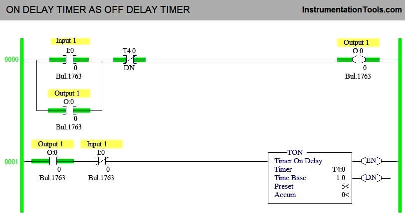
How to Interchange ON Delay Timer and OFF Delay Timer in a PLC
How to a Contactor and Timer relay Connection on delay ... In this video, we discuss how to a delay timer connect with contactor and how a delay timer work as an on delay and off delay also discuss wiring diagram and...

Time-Delay Electromechanical Relays Worksheet - Digital Circuits
Timer And Contactor Wiring Diagram Pdf - Wiring Diagram On delay timer circuit diagram wiring diagram contactor with push button circuit diagram of delay timer on off power off delay timer circuit diagram 2 way lighting circuit triggering transformer push button fan switch light activated switch circuit diagram wd081 text. Each component should be placed and linked to other parts in particular manner.
TIME DELAY RELAYS
Timer Switch Wiring Diagram - easywiring In the wiring diagram above it shows white neutral wire running to tork timer terminal 2. An intermatic timer switch saves electricity when it turns a water heater off at night and when it limits the amount of. Old double wall switch 300×255 Installing a Better Light Switch.
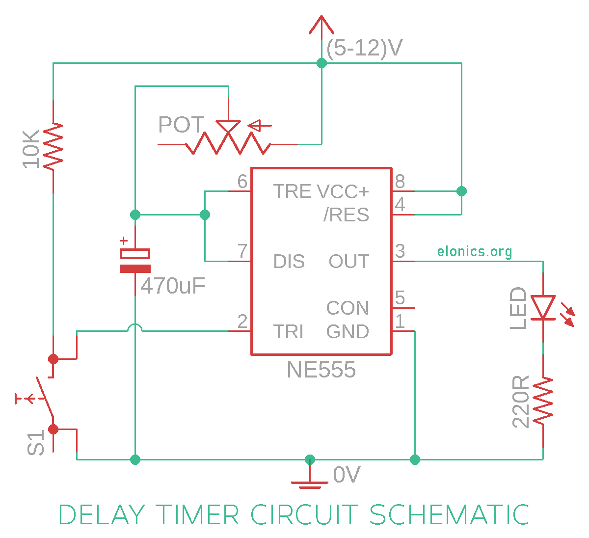
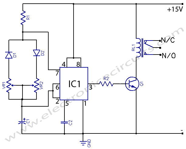
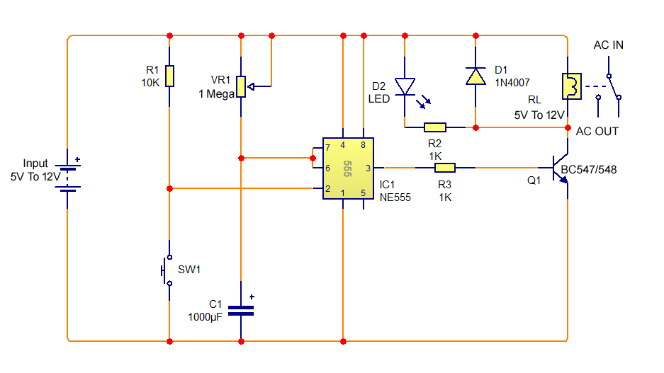
Adjustable Auto On Off Delay Timer Circuit Using 555 IC
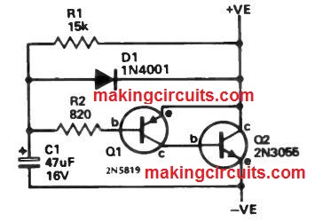
Simple Delay Timer Circuits Explained - Homemade Circuit ... Simple Delay Timer Circuits Explained. In this post we discuss the making of simple delay timers using very ordinary components like transistors, capacitors and diodes. All these circuits will produce delay ON or delay OFF time intervals at the output for a predetermined period, from a few seconds to many minutes.
Timer With On-Off Delay | Electronic Circuits
Fan Timer Wiring Diagram - easywiring Bathroom Extractor Fan With Timer Wiring Diagram. The Manrose Shower Fan is designed exclusively for safe ventilation within a shower Wiring of Timer Model FAN - SFT Diagram 2. D Earth Connection To all unitsThis wire should be sleeved in a greenyellow earth sleeve. How to wire in a new bathroom extractor fan with timer.

Omron H3CR OFF delay Timer | OFF Delay Timer working System and Connection diagram
PDF Multi-functional Timer relay. voltage, the time delay relay is ready to accept a trigger. When trigger is applied, the output is energized and timer delay (t) begins. Any application of the trigger during the time delay will reset the time delay (t) and the output remains energized. 14 SINGLE SHOT Upon application of input voltage, the time delay relay is ready to accept a

Defferance between On Delay Timer and Off Delay Timer
PDF Timing Diagrams Overview Timers - IDEC Corporation Timing Diagrams Overview Timers 834 Signal ON/OFF-Delay 1 Voltage is supplied to the coil at all times. When a maintained start signal is supplied, the contacts immediately transfer to the on state and the set time be-gins. When the set time has elapsed, the contacts transfer to the off state. The
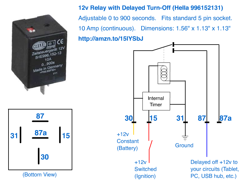
12v Delayed turn-off or turn-off (howto)
Time Delay Relay Basics: Relay Circuit and Applications Introduction. Time relay refers to a kind of relay whose output circuit needs to make an obvious change (or contact action) after adding (or removing) the input action signal in a specified and accurate time. It is an electrical component used in a circuit with a lower voltage or a smaller current to switch on or off a circuit with a higher voltage and larger current.

Motor-Control Systems: Relays (part c)
Off Delay Timer Relay Wiring Diagram - U Wiring Off Delay Timer Relay Wiring Diagram. Amarante Pruvost. August 20, 2021. Find Instant Quality Info Now. Get Results from multiple Engines. This Post Is About The Staircase Timer Wiring Diagram In The Diagram I Use The On Delay Timer Finder 8 Pin Relay Re Electrical Circuit Diagram Timer Diagram.

DC 12V 0 ~ 120 Minutes Adjustable Infinite Cycle Delay Timer Relay ON-OFF Switch
PDF Time Delay Relays - Application Data Time Delay is defined as the controlled period between the functioning of two events. A Time Delay relay is a combination ... (Off Delay, Single Shot & Watchdog). ... (see wiring diagrams below). Depending on the function, input voltage will either initiate the unit or make it ready to initiate when a trigger signal is applied. Trigger Signal: ...

on off delay timer connection and use
Car Interior Lights Delay Off Circuit

Sequence Control: Off-Delay – Basic Motor Control

20 Most Recent Amperite Dayton Solid State Timer On Questions ...

Using Time Delay Relays to Cycle a Traffic Signal
Simple On Delay Timer Circuit Diagram with IC555

Dave Lers : Workshop : Blog : Wiring a ST3PF Delay Off Relay

Time-Delay Electromechanical Relays Worksheet - Digital Circuits

On Delay Timer Connection Diagram and Testing - ETechnoG
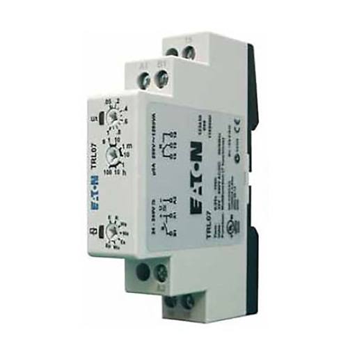
Timing Relay | Control Relays and Timers | Eaton

SOLVED: Dayton 6a859 off delay timer wiring - Fixya
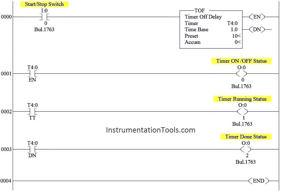
OFF Delay Timer using PLC - Timer Off Delay Instruction

Add fan to boiler: http://waterheatertimer.org/add-fan-to ...
Time Delay Relay | ON Delay Timer | OFF Delay Timer ...

Industrial Motor Control: Timing Relays

Time Delay Relay Circuit with 555
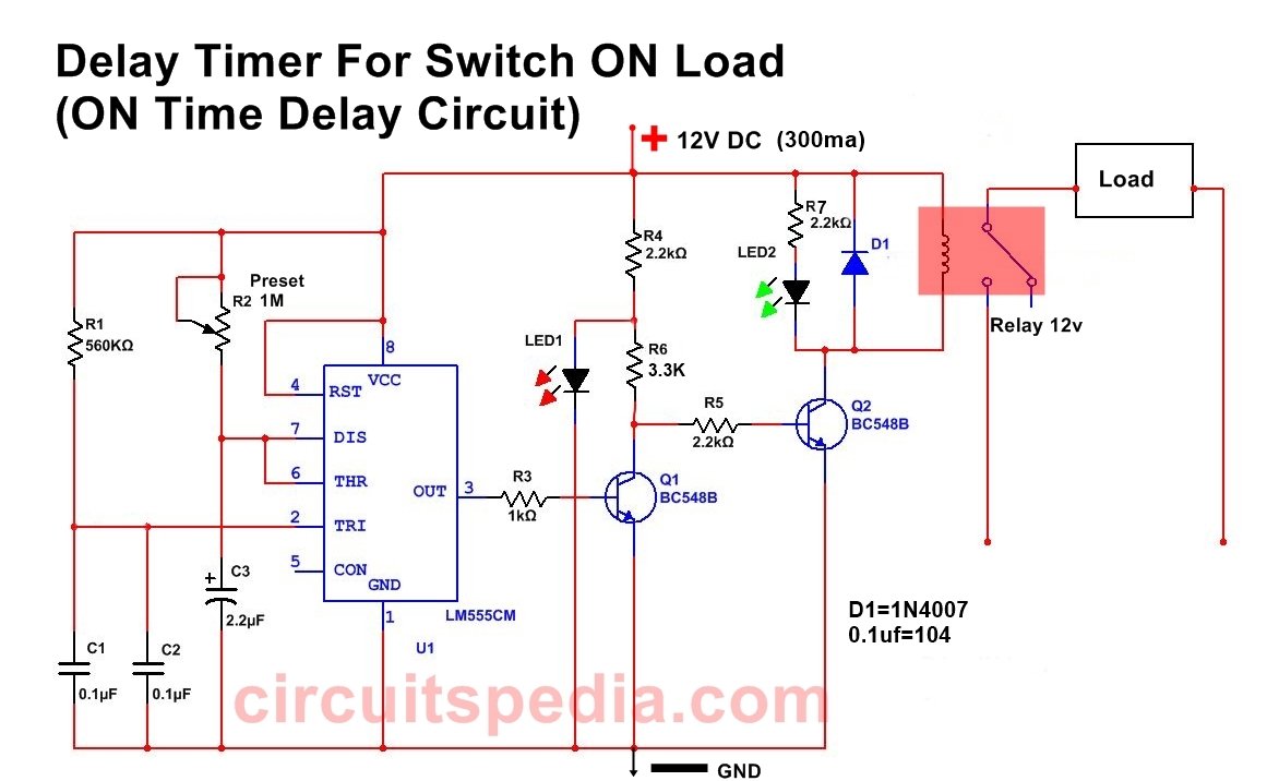
ON Delay Timer Circuit, Delay Timer For Switch ON, Switch On ...

circuit diagram for the delay timer. | Download Scientific ...

Timer Delay Relay DC 5V 12V 24V On Off Timer Module Trigger Cycle Dual MOS Delay Control Board with Digital Tube Display and Protective Shell for ...
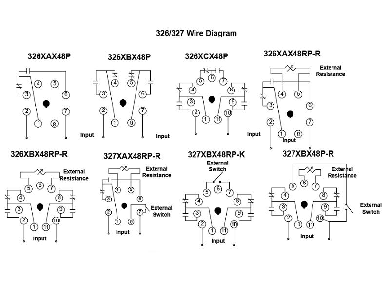
Item # 326XCX48P-010-115-125VDC, 326/327 Series - Time Delay ...

Industrial Motor Control: Timing Relays

Delay Timer Switch,GRT8-B1 AC/DC 12V~240V Mini Power Off Delay Time Relay DIN Rail Type
hotwaterwizard: dome delay relay

How to wire Dayton Off Delay Timer

China Power Off Delay Timer Relay Manufacturers, Suppliers ...

How to wire Dayton Off Delay Timer
on delay timer wiring diagram | 8 pin timer relay wiring diagram | Mian Electric


Komentar
Posting Komentar