40 cam displacement diagram
Kinematics of Cam Mechanisms Cams | Displacement Diagram Displacement diagrams: In a cam follower system, the motion of the follower is very important. Displacement Diagram. (4) Draw the cam profile for following conditions How to drawdisplacement diagram of cam profile? - Answers The cam diagram for the Isuzu Rodeo 1998 2.2 can be located at Rock Auto and Isuzu. You may be describing a plan diagram for a raw stone, or a profile for a cut diamond.
What is a Refractometer & How Does it Work - Cole-Parmer 05.03.2020 · What is a Refractometer? A refractometer is a simple instrument used for measuring concentrations of aqueous solutions. It requires only a few drops of liquid, and is used throughout the food, agricultural, chemical, and manufacturing industries.. How a Refractometer Works. When light enters a liquid it changes direction; this is called refraction.
Cam displacement diagram
› showthreadInventorCAM 2021 SP4 for Autodesk Inventor 2018-2022 (x64 ... Feb 17, 2022 · InventorCAM offers various means of creating control programs for multi-axis machining at 4- and 5-axis machining centers. The model is installed in the user defined processing plane, after which the system automatically calculates all the necessary displacement and rotation parameters for the workpiece zero. InventorCAM 2021 SP4 for Autodesk Inventor 2018-2022 ... InventorCAM 2021 SP4 for Autodesk Inventor 2018-2022 Multilingual (x64) File Size: 4.7 GB InventorCAM is a new generation CAD / CAM system developed by Israeli firm SolidCAM Ltd (Official distributor in Russia - Consistent Software). This system is a complete solution for automation of metalworking ... › vw-engine-calculatorEngine Calculator for Four Cylinder VW Engine - Aircooled Example: To determine the appropriate head combustion chamber volume needed to build an 1800cc engine with a compression ratio of 8.5:1, with 0.040″ deck height, you would plug in the following numbers:
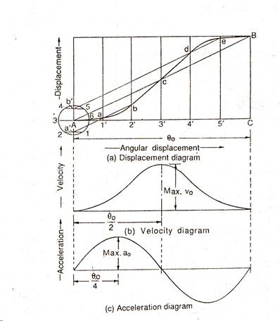
Cam displacement diagram. Displacement Diagram - DT Online A Displacement Diagram is essentially a graph which plots the movement of a cam follower against time. Since the cam's movement is usually constant then equal time intervals can be represented by equal distances along the horizontal axis and the resulting follower movement (or 'displacement'... Displacement diagram Cam follower design. Displacement diagram. Drawing cam profile. The displacement diagram is the graph plotted between the angular distance of the cam and the lift of the follower. Cam-Displacement Diagram | PDF | Classical Mechanics | Space 8. Displacement diagram A diagram plotted in a rectangular axis, it is used to show the relation between successive positions of the follower and the cam. Cam displacement diagram 1. Displacement Diagram A displacement diagram is a graph showing displacement of the follower plotted as a function of time. Degrees of cam rotation are plotted along the horizontal axis...
Cams are used to convert rotary motion into reciprocating motion - ppt... 39 Displacement diagrams Displacement is the distance that a follower moves during one complete revolution (or cycle) of the cam while the follower is in contact with the cam. Cam nomenclature & Displacement Diagrams - Engg Tutorials Cam nomenclature & Displacement Diagram for Different CAM Profiles. Displacement diagrams: In a cam follower system, the motion of the follower is very important. Cam - Wikipedia Displacement diagram. Fig. 2 Basic displacement diagram for a rotating cam. Cams can be characterized by their displacement diagrams, which reflect the changing position a follower would make as the surface of the cam moves in contact with the follower. In the example shown, the cam rotates about an axis. These diagrams relate angular position, usually in degrees, to … Cam profile and cam displacement diagram - YouTube Cam profile and cam displacement diagram. Смотреть позже. Поделиться.
Cam follower motions - Engineering Drawing - Joshua Nava Arts Angular displacement of cam. 2 Uniform acceleration and retardation motion is shown in Fig. What is the difference between displacement diagram of parabolic motion and modified uniform motion? How To Draw Displacement Diagram For Cam - Free Catalogs A to Z 2 hours ago Cam displacement diagram. 1. Displacement Diagram A displacement diagram is a graph showing displacement of the follower plotted as a function of time. Drawing Cam Displacement Diagram 8/11/2019 Drawing Cam Displacement Diagram. 2/2. Constructing the Cam Profile 1. ,onstruct the The distances are measured from the base line of the displacement diagram to the graphed cam... Gr 11 - Loci of a Cam Profile and Displacement Diagram - Page 108... A "How To Tutorial Video" on How to Draw a Loci of a Cam Profile and Displacement Diagram. Presented by Stefan Kleyn - Global Leadership Academy...
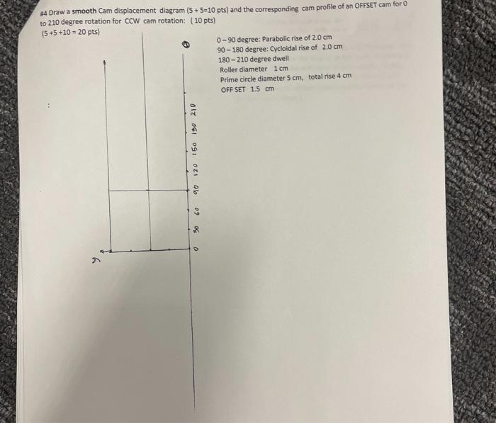
Solved #4 Draw a smooth Cam displacement diagram (5+5=10 ...
Cam Terminology and Displacement Diagram - mech4study Today we will learn about cam terminology and its displacement diagram. A cam is a mechanical member used to impart desired motion or displacement to a follower by direct contact.
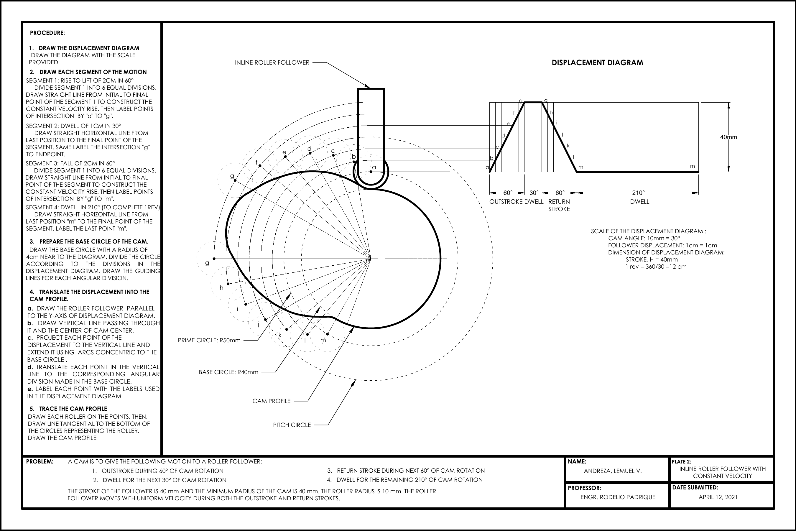
ANDREZA LEMUEL - PLATE 2
Cam — Wikipedia Republished // WIKI 2 Certain cams can be characterized by their displacement diagrams, which reflect These diagrams relate angular position, usually in degrees, to the radial displacement experienced at that position.
A computational approach to profile generation of different ...
Cam Terminology and Displacement Diagram - Automobile... Displacement Diagram: Angle of Ascent: It is the angle through which the cam turns during the time the The displacement diagram show show that the cam angular position ranges through a full...
Cam nomenclature & Displacement Diagrams - Engg Tutorials
CAMS - CAMS and Follower. Profile construction of CAMS... - StuDocu Profile construction of CAMS & Displacement diagram for Follower. kinematics of machinery(eme 202) cams module iv: cams introduction cam is.

Displacement Diagram - DT Online
Скачать Cam profile and cam displacement diagram - смотреть...

CAM. - ppt video online download
Traslochi Molise Traslochi Molise
Cam nomenclature & Displacement Diagrams - Engg Tutorials
Soil Classification and Identification (With Diagram) In the laboratory, casagrande’s liquid limit apparatus is used for determination of liquid limit of soil. The apparatus consists of a brass cup mounted on a hard rubber base as shown in figure 3.11. The brass cup can be raised and lowered to fall on the rubber base with the help of a cam operated by a handle. The cup is adjusted to fall from ...
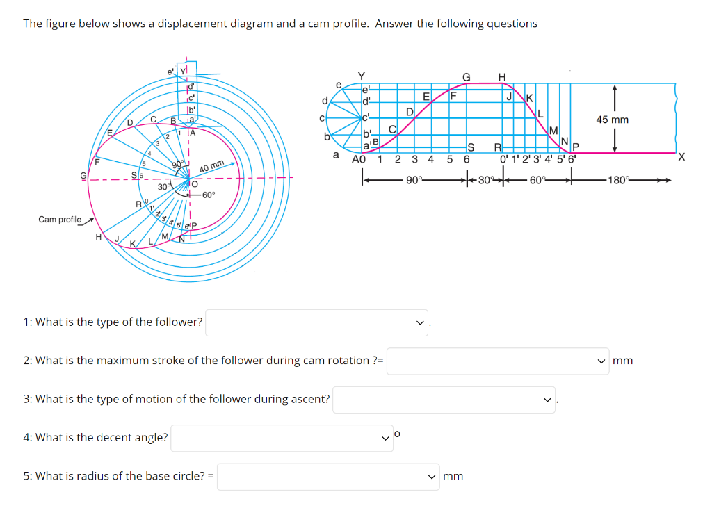
Solved The figure below shows a displacement diagram and a ...
ATLAS COPCO COMPRESSED AIR MANUAL CAM_cover_English_2014.indd 1 13/04/15 14:54. COMPRESSED AIR MANUAL 8th ... 1.5.2 Positive displacement compressors 20 1.5.3 The compressor diagram for displacement compressors 20 1.5.4 Dynamic compressors 22 1.5.5 Compression in several stages 23 1.5.6 Comparison: turbocompressor and positive displacement 23 1.6 ELECTRICITY 24 1.6.1 Basic …

Cam follower motions - Engineering Drawing - Joshua Nava Arts
Cam | Tractor & Construction Plant Wiki | Fandom 2 Basic displacement diagram. Certain cams can be characterized by their displacement diagrams, which Displacement diagrams are traditionally presented as graphs with non-negative values.

Cams - Theory Of Machines - Engineering Reference with Worked ...
PDF Gears, splines, and cams 2163 Classes of Cams 2163 Cam Follower Systems 2164 Displacement Diagrams 2169 Cam Profile Determination 2170 Modified Constant Velocity Cam 2172 Pressure Angle and Radius of.

CHAPTER 14: CAMS AND GEARS Displacement Diagrams ...
Subaru Outback EJ25 engines are always in stock ! All JDM Engine Displacement : 2.5; Model : SUBARU OUTBACK; Engine Name : EJ25 SOHC; Year : 2009; Subaru EJ25 S.O.H.C rebuilt Japanese VVTI engine for year 2009 for sale. Buy now. Page [1] 2 . We have the largest inventory of Subaru Outback engines. Most EJ25 Single overhead cam engines for Subaru Outback we sell are re-manufactured. EJ25 Subaru engines have head …

CHAPTER 14: CAMS AND GEARS Displacement Diagrams ...
Cam Displacement Diagram and Cam Profile Use... | Chegg.com Plot a displacement diagram and determine the required speed of the cam when the follower motion sequence is as follows: 1. Rise 1.5 in. in 1 s. 2. Dwell for 0.9 s. 3. Fall 1 in. in 0.5 s. 4. Rise 0.5 in. in...
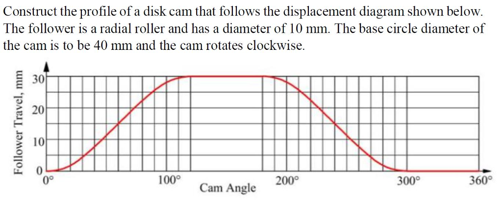
Solved Construct the profile of a disk cam that follows the ...
› yachts › new-hallberg-rassy-340New! Hallberg-Rassy 340 - Hallberg-Rassy The head sail has a small overlap which makes it easy to tack. There is also a possibility to get a self-tacking arrangement. The waterline is 10.1 m, no less than 1.01 m longer than the precursor 342. According to Frers speed diagram, a loaded Hallberg-Rassy 340 will log 7.31 knots in a 90 degree true wind angle with only 10 knots true wind.
Cam diagrams
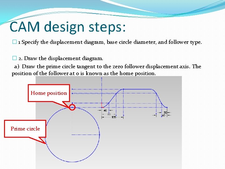
Cams Design 1. Introduction 2. Cams clasification 3. Desmodromic Cams 4. Followers clasification 5. Closure Joints clasification 6. Classification of Cams mechanisms 7. SVAJ Diagrams 8. Fundamental Law of Cams.

Construct a cam profile with knife edge follower having an ...
Valve timing - Wikipedia Valve timing diagram for a 4-stroke engine. With traditional fixed valve timing, an engine will have a period of "valve overlap" at the end of the exhaust stroke, when both the intake and exhaust valves are open. The intake valve is opened before the exhaust gases have completely left the cylinder, and their considerable velocity assists in drawing in the fresh charge. Engine …
Tutorial schedule changes q Original schedule cam follower
Displacement Diagram Displacement Diagram: (Re: cams) A drawing that represents the desired motion of the cam. The length of the diagram is equal to the circumference of the working circle.
eNotes: Mechanical Engineering
Cam - Infogalactic: the planetary knowledge core Certain cams can be characterized by their displacement diagrams, which reflect These diagrams relate angular position, usually in degrees, to the radial displacement experienced at that position.

HOW TO DRAW THE CAM PROFILE II OFFSET FOLLOWER II MOVES WITH SHM
› topics › engineeringBourdon Gauge - an overview | ScienceDirect Topics A typical 50 mm diameter tube has a displacement of up to 4 mm. Pressures of about 35 kPa to 100 MPa are typically measured. The movement may translate directly into a meter movement, or activate a displacement transducer that provides an electrical signal suitable for computer data acquisition.

Chapter 12. Cams - Engineering Design and Graphics with ...
Cams classification Displacement diagram: It is the plot of linear displacement (s) of follower V/S angular displacement (θ) of the cam for one full rotation of the cam.
Cam - Wikipedia
Cam - 3D CAD Models & 2D Drawings | Displacement diagram 2 Basic displacement diagram. Certain cams can be characterized by their displacement diagrams, which reflect the changing position a roller follower (a shaft with a rotating wheel at the end)...
Cam profile and displacement law | Download Scientific Diagram
Cam Terminology and Displacement Diagram CAM. A cam is a mechanical member used to impart desired motion or displacement to a follower by direct contact. It is widely used in automobile industries to direct opening and closing of inlet and...
Cams classification
› vw-engine-calculatorEngine Calculator for Four Cylinder VW Engine - Aircooled Example: To determine the appropriate head combustion chamber volume needed to build an 1800cc engine with a compression ratio of 8.5:1, with 0.040″ deck height, you would plug in the following numbers:
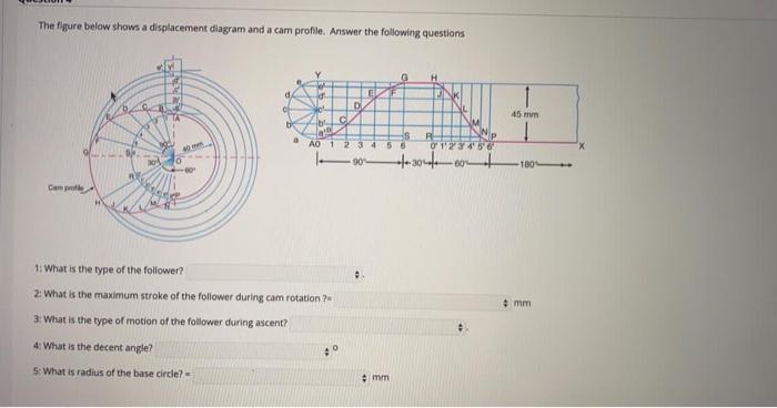
Solved The figure below shows a displacement diagram and a ...
InventorCAM 2021 SP4 for Autodesk Inventor 2018-2022 ... InventorCAM 2021 SP4 for Autodesk Inventor 2018-2022 Multilingual (x64) File Size: 4.7 GB InventorCAM is a new generation CAD / CAM system developed by Israeli firm SolidCAM Ltd (Official distributor in Russia - Consistent Software). This system is a complete solution for automation of metalworking ...
Chapter 6. Cams
› showthreadInventorCAM 2021 SP4 for Autodesk Inventor 2018-2022 (x64 ... Feb 17, 2022 · InventorCAM offers various means of creating control programs for multi-axis machining at 4- and 5-axis machining centers. The model is installed in the user defined processing plane, after which the system automatically calculates all the necessary displacement and rotation parameters for the workpiece zero.

CAM | pritamashutosh
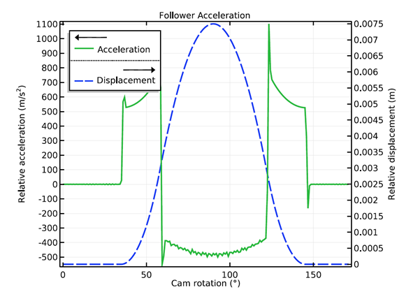
How to Model a Cam-Follower Mechanism | COMSOL Blog
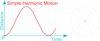
Study and Application of Harmonic movement of the Cam ...

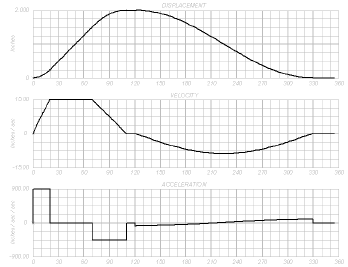
Motion analysis and plotting graph

Cam profile and follower displacement. | Download Scientific ...
UNIT III KINEMATICS OF CAM MECHANISMS INTRODUCTION A cam is a ...

Pitch Circle Problem 8.17 Construct the profile of a disk cam ...

Solved: "Cylindrical Cam Component Generator" Tutorial ...

3 | Page 11 | Mechanical Engg Diploma Simple Notes ,Solved ...
Solved] Draw a cam follower displacement diagram for the ...

The displacement diagram of the cam of 31-mm stroke ...
problems based on CAM Profiles (Solved) - Engg. Tutorials
Displacement Diagram - DT Online
ME232 CAM Handout

MECHANICAL BASICS AND PRINCIPLES: Solved problems based on ...
Solved Construct the cam profile for the case of a | Chegg.com


Komentar
Posting Komentar