40 ic 7400 pin diagram
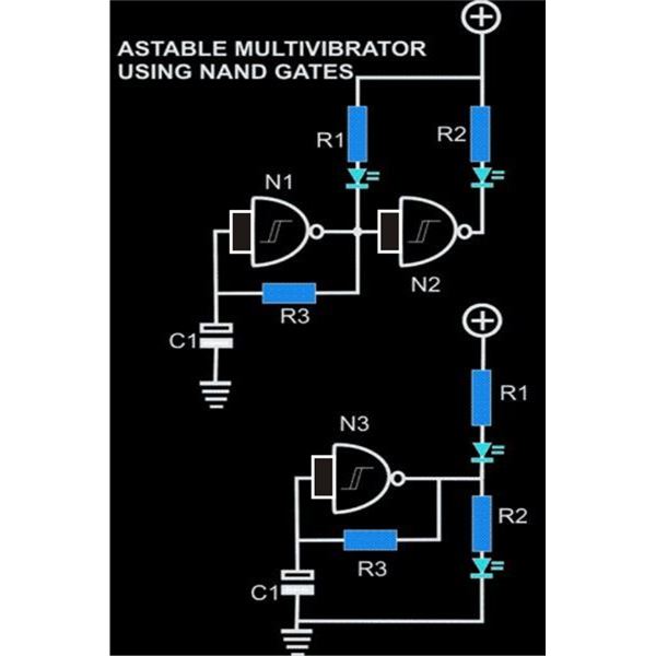
7400-series integrated circuits - Wikipedia 7400-series integrated circuits. From Wikipedia, the free encyclopedia. Jump to navigation Jump to search. The first part number in the series, the 7400, is a 14-pin IC containing four two-input NAND gates. IC 7400 Pin Diagram, Circuit design Learn about the 555 Timer IC - its symbol, pin connections, power supply, inputs and output. Also the 556 dual timer IC.
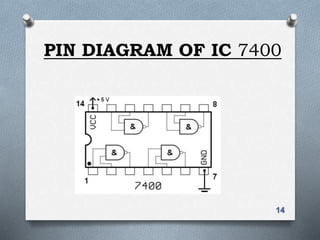
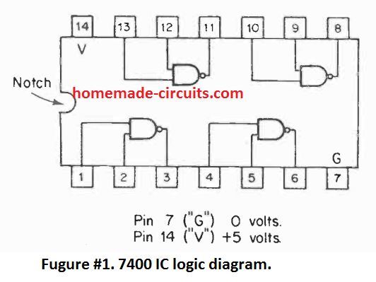
Pin on PINOUT | IC 7400 Pin Diagram, Circuit design explained Mar 26, 2020 - IC 7400 is fourteen pin Logic Gate IC. The IC 7400 consist of four NAND Gates. Pin diagram of IC 7400 explained here. Operating Condition and Electrical Characteristics of IC 7400 described here. The Internal Structure and Pin Description of IC 7400 explained detail.

Ic 7400 pin diagram
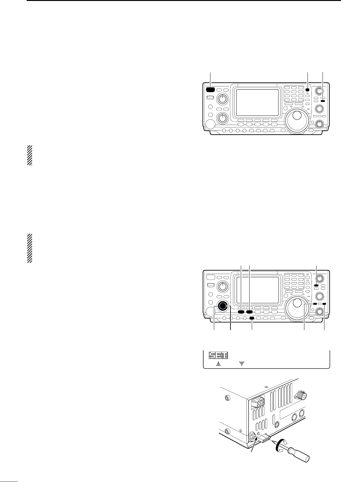
7400 Ic Diagram ! View the latest news and breaking news today IC 7400 : pin Configuration, Circuit, Specifications and. News Post. Details: IC 7400 Circuit Diagram using NAND Gate. News Post. Details: 7400 IC pinout diagram Integrated Circuits Elektropage.com. Related topics : Integrated Circuits > L165; 555-556 Timer info > 555 Astable... Icom IC-7400 Instruction Manual | PDF Icom IC-7400 Instruction Manual - Free download as PDF File (.pdf), Text File (.txt) or read online for free. (The diagram below describes the connection with compact switching power supply is the AGC DUP CMP TBW SCP uation to pin point an interfering signal. The 12 o'- clock position is on the... 7400 ic - Bing Pin diagram of IC 7400 explained here. The IC 7400 is a 14-pin chip and it includes four 2-input NAND gates. Every gate utilizes 2-input pins & 1-output pin, by the remaining 2-pins being power & ground.
Ic 7400 pin diagram. 7400 Ic #ic7400 Pin configuration of ic7400 (NAND Gate ic) B.Sc 6th sem #rcusyllabus. IC 7400 is the most popular logic family in integrated circuits. Texas Instruments has introduced the first logic chip namely SN5400 ... Digital Logic. Seven basic logic gates and how they work. Each animated diagram shows the input and output conditions for one of the seven logic functions in its two input form. Because gates are manufactured in IC form, typically containing two to six gates of the same type, it is often uneconomical to use a complete IC of six gates to perform a particular logic... GitHub - r0the/logi7400: Logisim 7400 series integrated circuits library The new Logi7400ic library provides a logical circuit appearance. Goal. This library aims to be a comprehensive 7400 series library for Logisim for designing logical circuits and for educational purposes. The library should be compatible both with original Logisim and logisim-evolution. 7400 Datasheet - ElectroSchematics.com 7400 IC is a Quad 2-Input NAND Gate that contains four independent gates each of which performs the logic NAND function. 7400 IC Circuit Diagram. 7400 package and pins.
Get started with NOT Gate IC | 7400 Series Tutorial 7400 IC is the most widely used TTL (Transistor-Transistor Logic) device in the world. It contains four independent two-input NAND gates. Commonly used AND gate IC is 7400. It has four independent NAND gates with standard pin configuration. The operating temperature is 70 degree celsius. 7400 Technical Data | Pin Number Home > Integrated Circuits > 74 Series > 74 Series. 7400 - 7400 Quad 2-Input NAND Gate Datasheet. Photograph. Features. RigPix Database - Icom - IC-7400 Icom IC-7400. SPECIFICATIONS. GENERAL. 600 ohm / 8-pin (Metal locking ring connector). Microphone input level: ? mV. This is the version approved for the european market. See also the US version IC-746 Pro. 7400 Ic Diagram Drivers IC 7400 : pin Configuration, Circuit, Specifications and. Drivers. Details: IC 7400 Circuit Diagram using NAND Gate. Details: 7400 IC pinout diagram Integrated Circuits Elektropage.com. Related topics : Schematic Circuits > 100 Watt Power Supply For Power Amplifier 7400 ic chip.
IC 7400 : pin Configuration, Circuit, Specifications and Its Applications The IC 7400 is a 14-pin chip and it includes four 2-input NAND gates. Every gate utilizes 2-input pins & 1-output pin, by the remaining 2-pins being power & ground. This chip was made with different packages like surface mount and through-hole which includes ceramic (or) plastic dual-in-line and flat pack. Draw the pin diagram of IC 7400. - Sarthaks eConnect ... Mar 16, 2020 · Draw the pin diagram of IC 7400. digital electronics; class-12; Share It On Facebook Twitter Email. 1 Answer +1 vote . answered Mar 16, 2020 by ... pin DIAGRAM OF IC 7400 - Datasheet Archive Abstract: data sheet 7400 IC internal diagram of 7400 IC IC 7400 7400 pin configuration IC 7400 data sheet 2SA1005 data sheet of 7400 Series TTL IC 7400 datasheet IC 7400 SERIES ALL DATA Text: straps and ankle straps which are grounded via a series resistance connection of about 1 M. Data... 7400 Ic Diagram! study focus room education degrees, courses... The IC 7400 consist of four NAND Gates. Pin diagram of IC 7400 explained here. Education. 4 days ago 7400 IC Chip Circuit Diagram 7400 package and pins showing pin outs . Here is some information about the 7400 Series TTL Integrated Circuits: PIN 2 PIN 3 PIN 1 PIN 4 PIN 5 PIN 6 PIN...
7400 IC pinout diagram - Integrated Circuits Elektropage.com
#ic7400 Pin configuration of ic7400 (NAND Gate ic) B.Sc 6th sem... #rcu #pinconfigurationofic7400#pinfunctionofic7400#ic7400#rcub#NANDgateIC#rcub physics#rcu physics.

IC-7400 Schematic - Icom
IC 7400 Pin Diagram, Circuit design, Datasheet... - ETechnoG The IC 7400 has fourteen pins including Vcc and ground pins. The simple pin diagram is shown below, Operating Condition of IC 7400: 1. The IC 7400 can operate from 4.5V Dc to 5.25V DC voltage. So power supply to the IC should be given in that range. 2. It can identify a signal as a high signal if the signal has the voltage above 2V. 3.

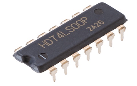
7400 NAND Gate IC (DIP-14 Package) – FactoryForward India
ICOM IC-7400 SERVICE MANUAL Pdf Download | ManualsLib IC-7400 transceiver pdf manual download. Icom IC-7400 Service Manual. Hf/vhf transceiver. Hide thumbs. Also See for IC-7400. Instruction manual - 116 pages Service manual - 84 pages.

IC 7400 Pin Diagram, Circuit design, Datasheet, Application ...
Pin Diagram Of Logic Gates - U Wiring Aug 09, 2021 · IC 7400 is fourteen pin Logic Gate IC. PIN configuration diagram 6 X-OR GATE. It can be used in the half adder full adder and subtractor. Twoinput gates are common but if only a single input is required such as in the 7404 NOTor inverter gates a 14 pin IC can accommodate 6 or Hex gates.

7400 Datasheet
Get started with NOT Gate IC | 7400 Series Tutorial May 22, 2017 · Pin-out diagram of 7404 NOT gate IC Each 7404 NOT gate IC has 6 NOT gates arranged as shown in the following figure. 14th pin is the Vcc and the 7th pin is the Ground. The outputs directly interface to CMOS, NMOS and TTL. It supports wide operating conditions and has large operating voltage range.

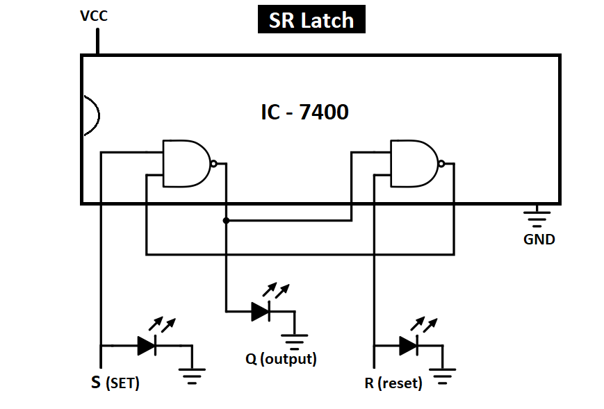
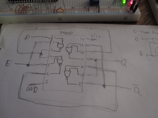
Practical Demo of S R Latch using 7400 NAND Gate and Push ...
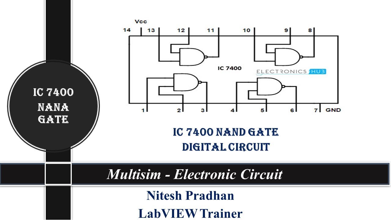
ic 7400 datasheet - Bing IC 7400 is fourteen pin Logic Gate IC. The IC 7400 consist of four NAND Gates. The NAND Gate is also called Universal Gate. The 7400 IC using NAND gate is most generally used transistor-transistor-logic (TTL) device. It can be built with 4-independent 2-input NAND gates.

Building Multiplexer and Demultiplexer using SN-7400 Series ...
7400 IC pinout diagram - Integrated Circuits Elektropage.com Keywords : 74xx, 7400, Integrated, Circuit, Ic, Pinout, Connection, Gate, Quad, Input, Output, Pals, NAND, GATE. >> Next: 4000 Series CMOS IC info.

Buy Logic IC Online in India. Hyderabad
ic 7400 pin diagram videos, ic 7400 pin diagram clips - clipzui.com #ic7400 Pin configuration of ic7400 (NAND Gate ic) B.Sc 6th sem #rcusyllabus. sagar 461 views8 months ago. 5:48. NAND Gate IC 7400 explained | Truth table with breadboard connection. EE Wave 15.920 views2 year ago. 20:18. ALL GATES IC Number, symbols, Truth Table with explanation and...

Logic NAND Gate Tutorial with NAND Gate Truth Table
LAB MANUAL (DIGITAL ELECTRONICS) - amittal Apparatus: logic trainer kit, NAND gates (IC 7400), wires. Theory: NAND gate is actually a combination of two logic gates: AND gate followed by NOT gate. The output of a two input X-NOR gate is shown by: Y = AB + A'B'. This can be achieved with the logic diagram shown in the left side.
ICOM IC-7400 SERVICE MANUAL Pdf Download | ManualsLib
Simple Circuits using IC 7400 NAND Gates - Homemade Circuit ... May 25, 2020 · In order to check a 7400 IC, you can apply power across pins 14 and 7. Keep pins 1 and 2 connected to positive supply, this will show the output as 0. Next, without changing pin 2 connection, connect pin 1 to 0 volts. This will enable the inputs to become 1, 0. This will cause the output to turn 1, illuminating the LED.

Logic Gate IC's: Concise information and various applications ...
Ic7400 #ic7400 Pin configuration of ic7400 (NAND Gate ic) B.Sc 6th sem #rcusyllabus.
GitHub - rishabhc32/flip-flops: Making Flip Flops and Latch ...
7400 ic - Bing Pin diagram of IC 7400 explained here. The IC 7400 is a 14-pin chip and it includes four 2-input NAND gates. Every gate utilizes 2-input pins & 1-output pin, by the remaining 2-pins being power & ground.

So erstellen Sie eine zweifarbige Sirenenschaltung
Icom IC-7400 Instruction Manual | PDF Icom IC-7400 Instruction Manual - Free download as PDF File (.pdf), Text File (.txt) or read online for free. (The diagram below describes the connection with compact switching power supply is the AGC DUP CMP TBW SCP uation to pin point an interfering signal. The 12 o'- clock position is on the...

T Flip Flop
7400 Ic Diagram ! View the latest news and breaking news today IC 7400 : pin Configuration, Circuit, Specifications and. News Post. Details: IC 7400 Circuit Diagram using NAND Gate. News Post. Details: 7400 IC pinout diagram Integrated Circuits Elektropage.com. Related topics : Integrated Circuits > L165; 555-556 Timer info > 555 Astable...
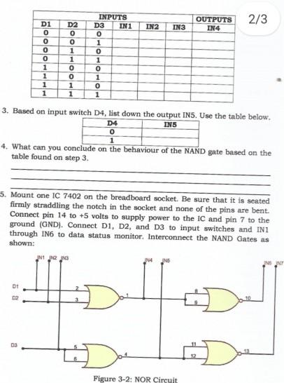
Solved Materials Needed: 1 pc IC - 7400 Quadruple 2-input ...

DL4EAI - Callsign Lookup by QRZ Ham Radio
Solved] Implement AND gate, OR gate and NOT gate respectively ...
Draw the pin diagram of IC 7402. - Sarthaks eConnect ...
IC7400 Nand Gate

Electronics - 7400 chip
Manual Icom IC-7400 (page 106 of 116) (English)
Results page 364, about 'IR phone'. Searching circuits at Next.gr
Mike McBike's unglaubliche unvollständige unverzichtbare IC-Liste

7400 Technical Data

Steffen Krumbholz: Schrittmotorsteuerung
NAND gate
7400 QUAD 2-Input NAND GATE
GitHub - rishabhc32/flip-flops: Making Flip Flops and Latch ...
TTL-series 7400 and 7486

74 Series Logic ICs | Electronics Club
Dealing with my lack of a latch IC by building one with 7400 ...
IC 7400 : pin Configuration, Circuit, Specifications and Its ...
Solved] 2. INV Verify the logic equivalence of a 7404 ...

Pin on Electronics
Simple Circuits using IC 7400 NAND Gates - Homemade Circuit ...
Digital Circuits Physical Lab

7400-series integrated circuits - Wikipedia
Der 555 wird 50 - und wer hats erfunden? -

Chloroform aerobic cometabolic biodegradation in a continuous ...

eleneasy.com – Electronics Engineering Made Easy


Komentar
Posting Komentar