41 powerflex 525 wiring diagram
Powerflex 525 Wiring Diagram Setup PowerFlex 525 - Digital Input Terminal 5 Wiring Diagram As shown above, the push-button circuit is straightforward. We're using the +24VDC contact on the drive pin 11, sending the signal through the contact and tying the other side to the "DigIn TermBlk 05". While the contact is open, the terminal... 520-QS001A-EN-E PowerFlex 520-Series Adjustable Frequency AC... Quick Start Guide for PowerFlex 523 and PowerFlex 525 AC Drives. PowerFlex 523 Catalog Number 25A PowerFlex 525 Catalog Number 25B. PowerFlex 523 Control I/O Wiring Block Diagram. SNK SRC. PowerFlex 520-Series Adjustable Frequency AC Drive.
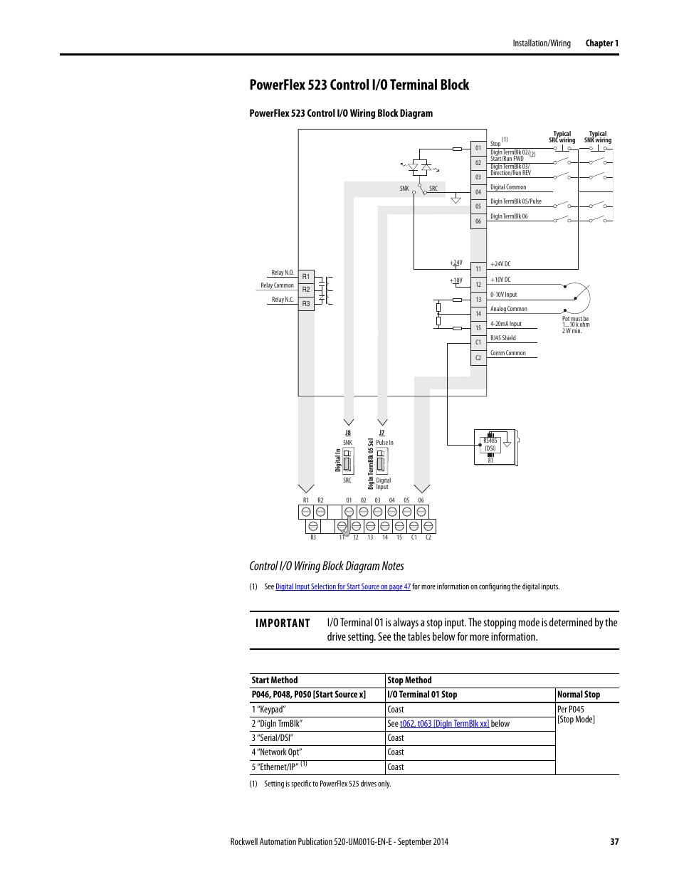
PDF 520-UM001B-EN-E PowerFlex 525 Adjustable Frequency AC Drive... Similar PowerFlex 525 drive sizes are grouped into frame sizes to simplify spare parts ordering, dimensioning, etc. A cross reference of drive Control I/O Wiring Block Diagram Notes. (1) See Digital Input Selection for Start Source on page 40 for more information on configuring the digital inputs.

Powerflex 525 wiring diagram
Drive Modernization Part IV PowerFlex 70 to PowerFlex 525 Is it time to upgrade your PowerFlex 70 to PowerFlex 525? This post will give you the instructions and information you need to modernize your drives. Let's start with the wiring of the PowerFlex 70 drive in comparison to the PowerFlex 525 drive. Please keep in mind, both drives are 24VDC for the inputs... PowerFlex 525 | Manualzz 3. Wiring Diagrams: a) Power Diagram: Shall include amperage ratings, circuit breaker frame sizes, circuit breaker continuous amp ratings, etc. as required for 5. 525 to 600 VAC, 3 phase. B. The VFD shall operate from an input frequency range of 47 to 63 Hz. PowerFlex 525 Low Voltage AC VFD. allen bradley 525 vfd manual - Bing | PowerFlex 525 Controller Manual PowerFlex 525 VFD Setup - Programming Parameters Wiring ... 800 2 0 Typical Wiring Diagrams For Push On Control Stations. Nema Manual Motor Low Voltage Starters Allen Bradley Indonesia.
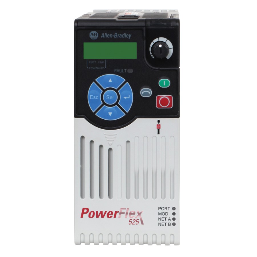
Powerflex 525 wiring diagram. Powerflex 525 Wiring Diagram For Your Needs Powerflex 525 Wiring Diagram from i.ytimg.com. Effectively read a wiring diagram, one has to know how the components within the program operate. For instance , in case a module is powered up and it also sends out a new signal of half the voltage and the technician would not know this, he'd think he... Powerflex 525 Wiring Diagram - Free Catalogs A to Z 3 hours ago Powerflex 525 Wiring Diagram Collection. A wiring diagram is a schematic type that uses abstract illustrated symbols to show all of the components of a system. Wiring diagrams are made up of two things: symbols that represent the components of a circuit, and lines that represent... PDF PowerFlex Low Voltage Drives Selection Guide PowerFlex 525 AC drives are ideal for machines with simple system integration and offer standard features including Safe Torque Off and a built-in port for EtherNet/IP. (1) For the corresponding wiring diagram, see page 137. Rockwell Automation Publication PFLEX-SG002L-EN-P - August 2017. PDF PowerFlex 525 AC Drive PowerFlex 525 AC Drive. Additional Information. PowerFlex 520-Series Technical Data, publication 520-TD001 PowerFlex 520-Series User Manual # For selection information, refer to Appendix A of the Wiring and Grounding Guidelines for Pulse Width Modulated (PWM) AC Drives, publication...
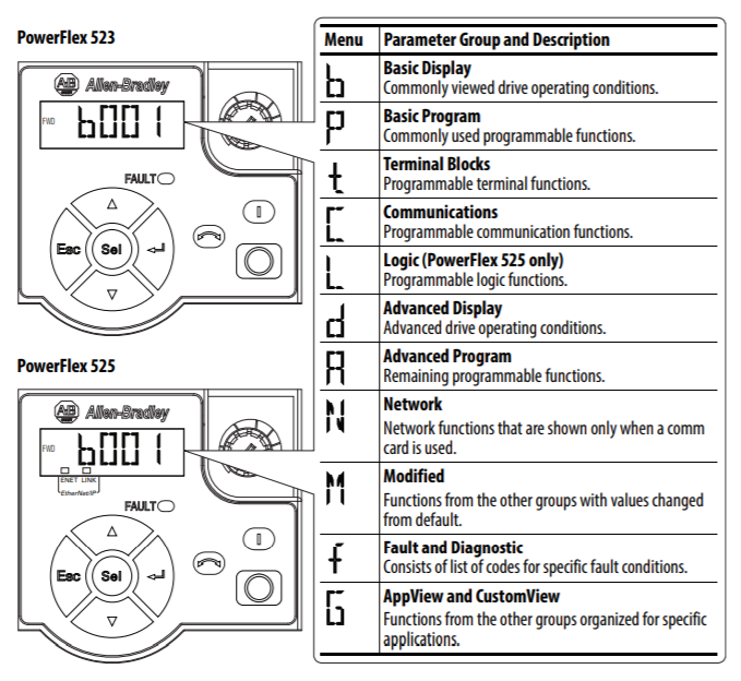
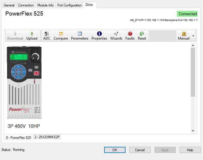
Powerflex 525 control i/o wiring block diagram | Rockwell Automation... PowerFlex 520-Series Adjustable Frequency AC Drive. PowerFlex 525 Control I/O Wiring Block Diagram. 04. 05. For three wire control use a momentary input. on I/O Terminal 02 to command a start. PDF 520-TD001B-EN-E PowerFlex 525 AC Drive Specifications Technical... The PowerFlex® 525 AC drive delivers an innovative design that is remarkably versatile and can The PowerFlex 525 provides general purpose control for applications ranging up to 30 HP and 22 kW. resistors. • A jumper to switch between 24V DC sink or source control for control wiring flexibility. • Power Flex 525 Manual | PDF | Fuse (Electrical) | Electrical Wiring PowerFlex 525, PowerFlex 525 drive or PowerFlex 525 AC drive. Parameter numbers and names are shown in this format: P 031 [Motor NP Volts] Name Number Group b = Basic Display P = Basic Program t = Terminal Blocks C PowerFlex 523 Control I/O Wiring Block Diagram Series A 01 02 03 SNK. Speed control of three phase induction motors using PowerFlex 525 PowerFlex 525 drives, which suggest a power rating of 0.4 kW to 22. kW (0.5 to.30 Hp) with global voltage classes of 100v to 600Vand they Select Ethernet\IP driver for PLC and Drive not. require for wire these two controllers and it Require Ethernet cable. Figure 7. Ladder diagram for VFD control.
Power Flex 525 "Wiring Diagram" - plc247.com The Powerflex 525 inverter is a series of Rockwell's 520 inverter series, which is the new generation of Component inverters from Allen-Bradley. The Powerflex 520 inverter series was born to meet Rockwell's Logix platform in common applications requiring inverters. ALLEN-BRADLEY POWERFLEX 525 USER MANUAL... | ManualsLib Page 43 Installation/Wiring Chapter 1 • PowerFlex 525 drives are not intended to be used on public low-voltage networks which supply domestic premises. Appendix Control Diagrams This chapter contains various diagrams on the PowerFlex 525 functions and behaviors. PDF PowerFlex 40 and 40P Drives to PowerFlex 525 Drives Migration Guide PowerFlex 525 Control Wiring and Terminals. Terminal Comparison Summary. To replicate the wiring of the PowerFlex 40 or 40P drive, the wiring diagrams will show the respective drives internally sourced (referenced to common) and externally sourced (+24V DC user supply), as examples. Powerflex 525 Wiring Diagram For Your Needs Powerflex 525 Wiring Diagram from i.ytimg.com. Effectively read a wiring diagram, one has to know how the components within the system operate. For instance , when a module is usually powered up also it sends out a signal of 50 percent the voltage in addition to the technician would not know this...
Position StepLogic With the PowerFlex 525 – CED Solution ...
allen bradley 525 vfd manual - Bing | PowerFlex 525 Controller Manual PowerFlex 525 VFD Setup - Programming Parameters Wiring ... 800 2 0 Typical Wiring Diagrams For Push On Control Stations. Nema Manual Motor Low Voltage Starters Allen Bradley Indonesia.
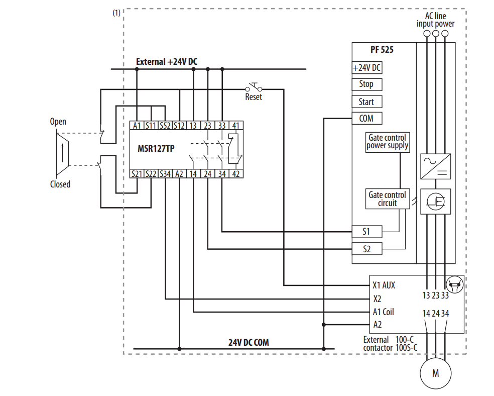
Safety Function: Door Monitoring, SAFETY-AT124A-EN-P
PowerFlex 525 | Manualzz 3. Wiring Diagrams: a) Power Diagram: Shall include amperage ratings, circuit breaker frame sizes, circuit breaker continuous amp ratings, etc. as required for 5. 525 to 600 VAC, 3 phase. B. The VFD shall operate from an input frequency range of 47 to 63 Hz. PowerFlex 525 Low Voltage AC VFD.

Testing A Powerflex 525 With Connected Components Control Bar ...
Drive Modernization Part IV PowerFlex 70 to PowerFlex 525 Is it time to upgrade your PowerFlex 70 to PowerFlex 525? This post will give you the instructions and information you need to modernize your drives. Let's start with the wiring of the PowerFlex 70 drive in comparison to the PowerFlex 525 drive. Please keep in mind, both drives are 24VDC for the inputs...

Drive Modernization Part VI PowerFlex 40 to PowerFlex 525 ...
520-UM001B-EN-E PowerFlex 525 Adjustable Frequency AC Drive ...

PowerFlex 525 VFD Setup - Programming Parameters Wiring ...
PowerFlex Low Voltage Drives Selection Guide

Drive Modernization Part III 1305 to PowerFlex 525 | Horizon ...
Powerflex 523 control i/o terminal block, Powerflex 523 ...
Bulletin 160 SSC Variable Speed Drives to PowerFlex 525 AC ...
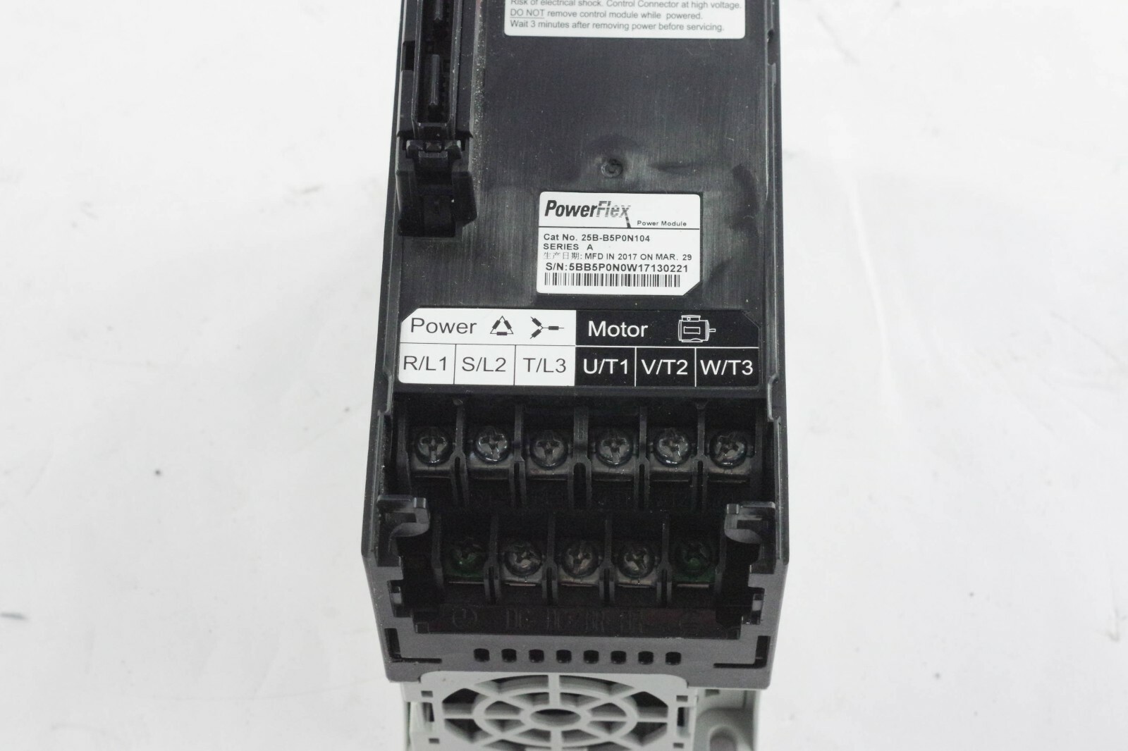
Allen-Bradley 25B-B5P0N104 Powerflex 525 1HP Drive for sale ...

Graphical User Interface of the application developed ...

PowerFlex S4 and Kinetix ERS4 Advanced Safety
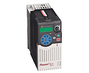
PowerFlex 525 AC Drives | Allen-Bradley Denmark
PowerFlex Compact-class AC Drives on Modbus Building Block ...
PowerFlex® Low Voltage AC Drives Selection Guide

Allen Bradley Power Flex 525 "Basic Setup" - plc247.com
Powerflex 525s, Safety Circuits and monitoring - Page 2 ...

Powerflex 525 control i/o terminal block, Powerflex 525 ...
AB PowerFlex 525 AC Drivers Keypad for Replacement | VICPAS

POWER FLEX 523 DEVICE NET COMMUNICATION - Allen Bradley ...

Allen Bradley PowerFlex 525 Compact Low Voltage AC Drive, For ...

PowerFlex 525 VFD Setup - Programming Parameters Wiring ...

PowerFlex 40 Adjustable Frequency AC Drive - PDF Free Download

PowerFlex 525 VFD Setup - Programming Parameters Wiring ...

Micrologix 1100 "Modbus RTU" PowerFlex 525 Tutorial - plc247.com
PowerFlex Drives

UL508A Listed Drive Control Panel, Allen Bradley AC PowerFlex ...

25B-D4P0N114 | Allen-Bradley | PowerFlex 525 Series AC Drive

PowerFlex 525 Manual - User Manuals Online

System wiring, Understanding the i/o image, System wiring ...
520-TD001G-EN-E PowerFlex 520-Series AC Drive Specifications ...

Allen Bradley Powerflex VFD - InstrumentationTools
ALLEN-BRADLEY POWERFLEX 525 USER MANUAL Pdf Download | ManualsLib

PowerFlex 525 Parameter, Input and Output Programming ...
Introduction to Allen-Bradley PowerFlex Drives with Ethernet ...
Open Access proceedings Journal of Physics: Conference series

Next Generation Guardmaster Safety Relay (GSR) Wiring Diagram ...

Multi-Drive Control – CED Solution Consultants Resource Center
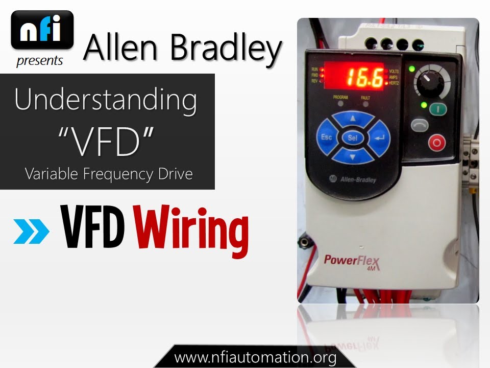
Allen Bradley Powerflex 4M- Understanding VFD Wiring

Drive Modernization Part IV PowerFlex 70 to PowerFlex 525 ...


Komentar
Posting Komentar