43 digital clock circuit diagram
PDF Design, Implementation and Simulation of 24h Digital Clock Circuit A digital clock is a type of clock that displays the time digitally. Instead of the rotary mechanism of electromechanical clock, it uses digital 1. The word description of the circuit behavior is stated, which is accompanied by obtaining a state diagram, a timing diagram, or other related information. Digital Clock Circuit Using 16x2 LCD Display - Homemade Circuit... This digital clock has just two main components, the Arduino and LCD display. The Arduino is the brain of the clock, which does mathematical and logical functions to updates the clock every second. The arduino can be powered externally from DC jack from 7 volt to 12 volt. Circuit diagram
Learning Sequential Logic Design for a Digital Clock... - Instructables Digital clocks have been built by countless electronics hobbyists over the world. So why have I chosen to implement that? The working of the block diagram is explained in detail here. Parts of this section might seem like the repetition of he logic of the circuit discussed before, but bear with me.

Digital clock circuit diagram
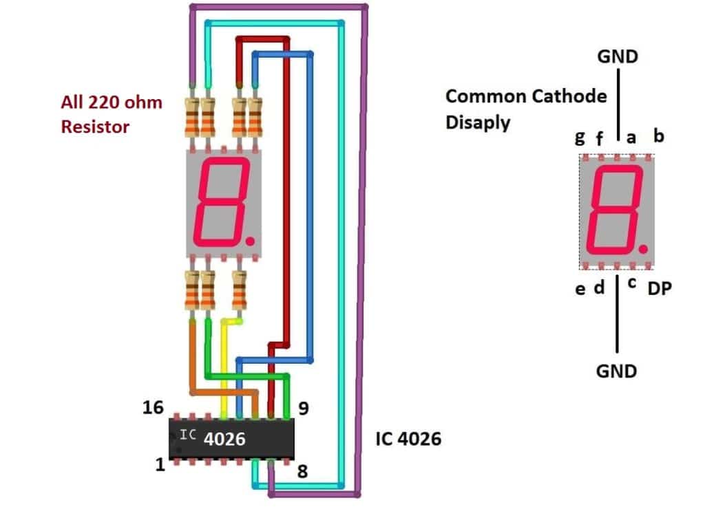
24 Hour Digital Clock and Timer Circuit - Engineering Projects This circuit here, "24-Hour Digital Clock and Timer Circuit" is a simple circuit with two different applications as reflected through the name 24-hour clock The Circuit of a versatile 24-Hour Digital Clock and Timer Circuit is described below in detail. First, let's go with some of its unique features. Circuit Diagram - Digital Clock Digital Clock using PIC Microcontroller and DS1307 RTC - Circuit Diagram. I hope that you can easily understand the circuit diagram. The circuit is powered using a 5V power supply. 8MHz crystal is connected to PIC Microcontroller to provide necessary clock for the operation. Circuit Diagram for 7 Segment Display Digital Clock Main Circuit Diagram. Pulse Generator for Digital Clock. IC 4026 Pin Configuration. NOTE: This clock circuit will show 12:00 as 00:00 at midnight and also at noon. The circuit needs clock signal to increment the counts, this is provided by the below circuit which outputs 1 pulse every minute.
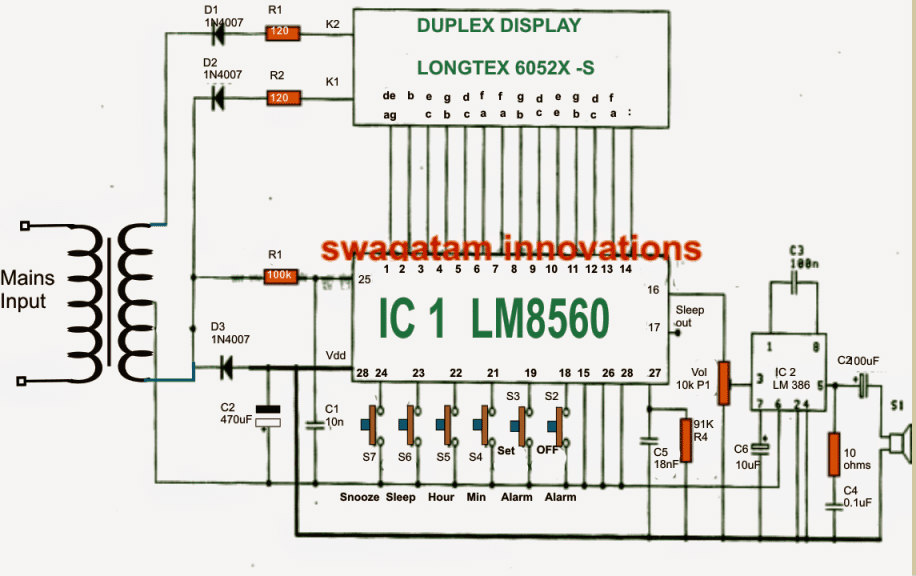
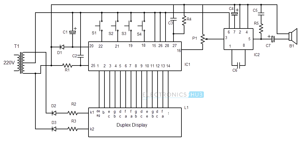
Digital clock circuit diagram. Circuit diagram for digital clock ~Circuit diagram Circuit diagram. Wednesday, October 15, 2014. HOME» circuit » Circuit diagram for digital clock. 12H/24H Digital Clock Circuit - Online Digital Electronics Course 12h/24h Digital Clock Circuit Design Using 7493. The 4 blocks of a digital clock are. 1 Hz clock generator to generate 1 PPS (pulse per second) signal to the seconds block. HOURS block - depending on whether it is a 12 or 24H clock, will have a divide 24 or divide by 12. LM8560 Digital clock circuit diagram with alarm | ElecCircuit.com LM8560 is digital clock circuit IC that electronic amateurs are most interested. And The clock ICs that most popular are LM8361, MM5387, Unfortunately I highly recommend this clock circuits features to work for less than the original circuits. But there are advantages due to having output in Duplex LED... Digital Clock Circuit Diagram Using 7490 - PCB Diagram in pictures database circuit diagram of 7 segment digital clock just download or read digital clock. Scroll to continue with content. This section is designed to display the time in hours and minutes format and is wired such that it functions in 24-hour mode.
Digital Clock Circuit Diagram Arduino UNO | Hack The Developer Digital Clock can be made in Arduino by displaying the time on the LCD Screen. Components Required for making digital clock in Arduino A circuit layout can be described in several ways. For this project (How To Connect LCD 16×2 Display To Arduino), we are using a physical layout diagram... Clock signal - Wikipedia In electronics and especially synchronous digital circuits, a clock signal (historically also known as logic beat) oscillates between a high and a low state and is used like a metronome to coordinate actions of digital circuits. A clock signal is produced by a clock generator. Digital Clock Circuit Diagram Schematic Using Counters - Free... This is circuit diagram of digital clock using CD4026. Therefore, if you do not want to use microcontroller. You can still design a digital A digital clock is shown named as circuit diagram of digital clock using counters! It's my st& that just looking at the digital clock circuit diagram... Digital Clock Circuit Diagram Using 4026 - 3 - I'm having some... Circuit diagram digital clock using gates clock using discrete components. English a digital counter based on the cmos 4026 decade counter & 7segment display driver ic. The least absolute shrinkage and selection operator lasso estimates model coefficients and these estimates can be used to select...
Digital Clock using 8051 Microcontroller with RTC DS1307 8051 based Real time clock is a digital clock to display real time using a RTC DS1307, which works on I2C protocol. DS1307 sends time/date using 2 lines to the microcontroller. Circuit connections are simple to understand and shown in the above diagram. PDF Report | 5.1 Clock Circuits Introduction. Clock Circuits. Bi-Stable Logic Devices. Counters. Shift Registers. A Simple ALU. Introduction The logic circuits discussed in Digital Electronics Module 4 had output states that Timing Diagrams Truth tables are not always the best method for describing the action of a... Simple Digital Clock Circuit Diagram - nerv "> Electronic Circuit Diagram Hours Clock - Simple Digital Clock Circuit Diagram. As May Be Witnessed In The Given Diagram The Heart Of The Circuit Is Formed By The Ic1 Lm8560 Which Is Assigned With The Following Outputs Ter minals - Simple Digital Clock Circuit Diagram. Digital clock design verilog_ digital electronic clock circuit diagram... Design requirements: Adopt digital circuit laboratory, design timer circuits to connect to the BCD digital tube, perform digital clock function Design of digital clock (40) Title Contents: is defined in the following claims a clock structure type: Then, programming analog clock displayed on the screen.
Scorpionz - Electronic Circuits and Microcontroller Projects ...
How to Make a Digital Clock: 11 Steps (with Pictures) - wikiHow Digital clocks can be used to tell time at a glance. They became quickly more popular than the older sweep With the perfecting of multivibrator chips, electrical circuits could be built that could accurately keep Do a Google image search for "circuit diagram of a digital clock," you'll see many examples.
Simple Digital Clock using LM8650 IC Circuit - Homemade ...
Circuit diagram of digital clock ds1307 using pic microcontroller Basic block diagram of digital clock interfacing with microcontroller is given below: In I2C serial communication, one device acts as a slave and other As shown in above circuit diagram, SCL pin of ds1307 is connected to SCL pin of microcontroller. It is used to synchronize serial data on serial wire.

Figure 5 from Bengali character based digital clock using 13 ...
Circuit Wiring Solution: Digital Clock Circuit Diagram The complete circuit diagram is shown in Fig. 1. Heart of the system is lC2, National's MM5402 clock chip. It is an MOS monolithic large scale As shown in the diagram, 9-volt DC supply derived by diode D3 and capacitor Cl is fed to the counting circuit of the clock chip at pin 29 through a lk resistor.

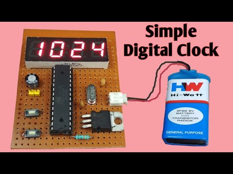
Simple Digital Clock
7 Segment LED Digital Clock with IC MM5314N - Schematic Design This is the circuit diagram of digital clock based on IC MM5314N. The clock display uses 6 pieces of 7 Segment LED with format HH:MM:SS. The power supply for this.
How to make a simple circuit diagram of a digital clock - Quora
Make Real Time Digital Clock Using ATmega328P-PU... - YouTube This Video Tutorial Also Contains Schematic Circuit Diagram Of Real Time Digital Clock & Also attached a link to the programming code and boot loader code for Arduino and Micro Controller IC To Make Digital Clock.
Easy digital clock | Atmega328p chip 7 segment clock | JLCPCB
PDF Designing Digital Circuits Designing digital circuits using hand-drawn diagrams is an entirely reasonable thing to do for circuits of moderate size, and The central disk shows the decimal equivalents of these binary values, and we'll refer to this diagram as the binary number clock since it kind of resembles an analog clock face.

Pin on clock
Digital Clock Circuit Diagram Schematic Using Counters Digital Clock Circuit Diagram of different kinds have been built by countless hobbyists over the world. A digital clock is shown named as circuit diagram of digital clock using counters! Usual digital clock circuit diagram that are based on decade counters have an hour counter from 0 -23.
Digital Alarm Clock
How to make a simple circuit diagram of a digital clock - Quora I'm having some trouble with "circuit diagram", as that seems rather specific to the electrical flows and would need to show conductors, transistors Such a diagram would be immense and complicated. 40 years ago, Heathkit had an early digital clock - I think they used early digital ICs with chips with...

Digital clock by using mod-n counter digital circuits ...
digital clock circuit | Electronics Forum (Circuits, Projects and...) digital clock circuit. Thread starter obnikon. Start date May 8, 2007. I found the data sheet and it is contain the diagram. Can you help me a little bit and now show me how to connect the seconds to minuts?
Design a digital clock circuit, which includes 4 | Chegg.com
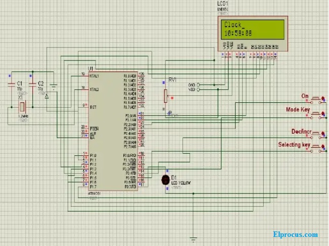
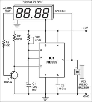
Digital Clock Circuit Diagram Digital Clock Circuit Diagram. After the alarm is fixed, the pin of an alarm is connected to VCC through the switch. This is all about digital clock circuit, which is designed by using a Microcontroller AT89C51, Preset, Piezo Buzzer, Buzzer and an LCD display.
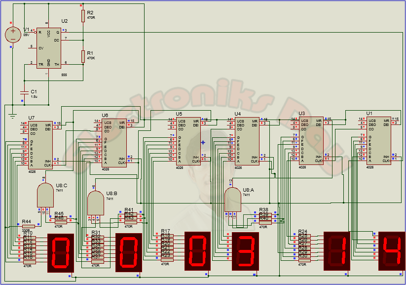
Digital Clock Circuit Using IC 555 and IC 4026 – DIY ...
clock circuit : Meter Counter Circuits :: Next.gr This page contain electronic circuits about Clock Circuits at category clock circuit : Meter Counter CircuitsCircuits and Schematics at Next.gr. General Dynamic LED digital clock have no timekeeping function, just add here a simple circuit it can bring the whole point timekeeping function...

clock - How Do I modify This Circuit using a push button ...
digital clock circuit diagram datasheet... - Datasheet Archive Abstract: simple block diagram for digital clock digital clock circuit diagram sony tv circuit diagram CX20051 si555 CX20051A temperature circuit diagram in ecu 2SA530 digital temperature circuit diagram Text: dynamic range test circuit — 188 — SONY« CX20051A Digital input signa...
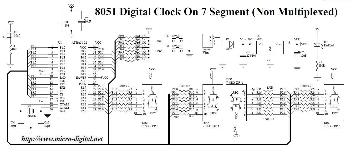
8051 Digital Clock On 7 Segment (Non Multiplexed) | Micro Digital
Circuit Diagram for 7 Segment Display Digital Clock Main Circuit Diagram. Pulse Generator for Digital Clock. IC 4026 Pin Configuration. NOTE: This clock circuit will show 12:00 as 00:00 at midnight and also at noon. The circuit needs clock signal to increment the counts, this is provided by the below circuit which outputs 1 pulse every minute.

Digital clock electronic project using PIC16C54
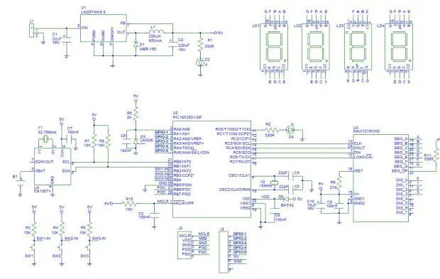
Circuit Diagram - Digital Clock Digital Clock using PIC Microcontroller and DS1307 RTC - Circuit Diagram. I hope that you can easily understand the circuit diagram. The circuit is powered using a 5V power supply. 8MHz crystal is connected to PIC Microcontroller to provide necessary clock for the operation.
Digital Timer : Circuit Diagram and Its Working Principle
24 Hour Digital Clock and Timer Circuit - Engineering Projects This circuit here, "24-Hour Digital Clock and Timer Circuit" is a simple circuit with two different applications as reflected through the name 24-hour clock The Circuit of a versatile 24-Hour Digital Clock and Timer Circuit is described below in detail. First, let's go with some of its unique features.
DIY Digital Clock with Temperature Display using PIC Controller

Pin on Electronics

DIY Digital Clock With 7 Segment LED Display : 8 Steps ...

AT89C2051 6 Digit LED Electronic clock parts Digital Clock ...
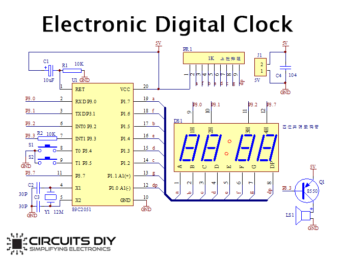
Electronic Digital Clock - Hackster.io
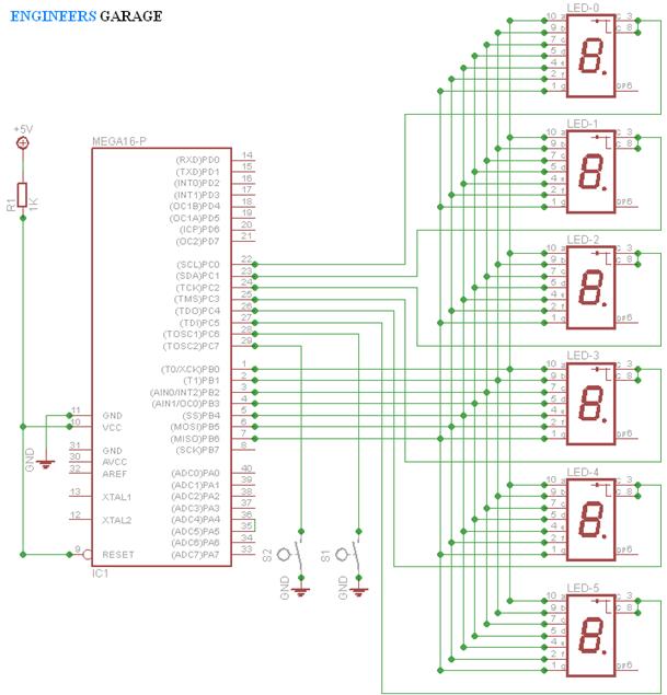
Digital Clock using Seven Segment Display and ATMega16 ...

LM8365 digital clock circuit board - ElecCircuit.com

Digital Clock Circuit using 8051 Microcontroller and DS12C887 ...

LM8560 Digital clock circuit diagram with alarm | ElecCircuit.com

WHDTS 4-Digit Digital Clock Kits with PCB for Soldering Practice Learning Electronics with English Instructions
digital clock under Repository-circuits -32046- : Next.gr

Will this Digital Clock Circuit work? : r/AskElectronics

Galactic Electronics Projects- 12 Hour Digital Clock

Building Clock with CMOS — Lynne Yun Design
Digital Clock Using 4026 IC

Digital Clock But Without a Microcontroller [Hardcore ...

Led Clock - Jose Pino's Projects and Tidbits.
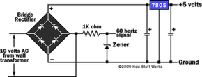
Circuit Diagram - How Digital Clocks Work | HowStuffWorks

How to Build a High Quality LED Digital Clock - Bright Hub ...
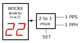
12H/24H Digital Clock Circuit - Online Digital Electronics Course

Digital Clock Circuit using 8051 Microcontroller and DS12C887
Auto Snooze for Digital Alarm Clocks | Detailed Project Available

Complete circuit diagram of Bangla character based digital ...

Simple Digital Clock
Digital Clock without Microcontroller
Clock Integrated Circuits
Digital Timer | ELECTRONICS PROJECTS

Some of the circuits I designed are below. Some of them ...


Komentar
Posting Komentar