43 pressure enthalpy diagram refrigeration cycle
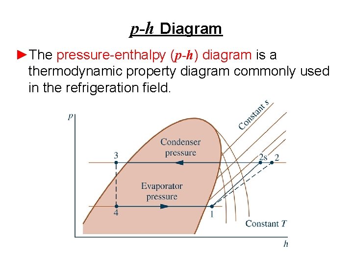
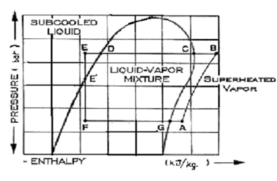
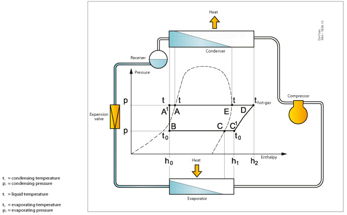
Refrigeration process, pressure/enthalpy diagram: Pressure ... Refrigeration process pressure-enthalpy diagram The condensed refrigerant in the condenser in a state that lies on the line for the boiling point of the liquid. Liquid, thus, the temperature tc, pressure pc also called saturated temperature and pressure. Pressure Enthalpy Diagram - engproguides.com On the P-H diagram, pressure is indicated on the y-axis and enthalpy is indicated on the x-axis. Typically enthalpy is in units of Btu/lb and pressure is in units of pounds per square inch (psi). The upside down U figure shown on the diagram designates the points at which the refrigerant changes phase.
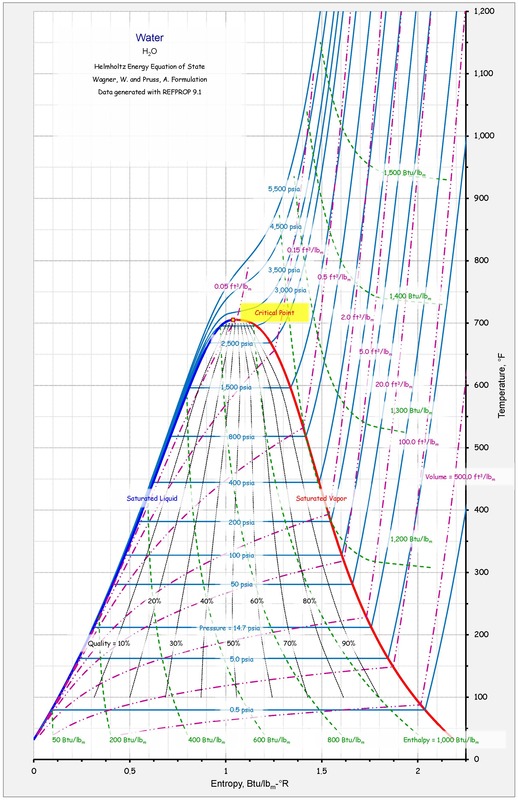
PLOTTING THE A/C CYCLE ON A PRESSURE-ENTHALPY ... Pressure-enthalpy diagram for water PLOTTING THE COOLING CYCLE AMollier diagram(another name for a pressure- enthalpy diagram) locates system operating pres- sures on the vertical (y) axis and enthalpy values on the horizontal (x). Physical properties of the axis refrigerant are represented by a curve that roughly resembles a thumb or a tongue.

Pressure enthalpy diagram refrigeration cycle
PDF Pressure-enthalpy Charts and Their Use - Rses The most common type of pressure-enthalpy diagram is shown in Figures 1A through 1H. They show all five properties for a specific refrigerant in present-day use. Pressure is listed along the right and left borders in psia. Horizontal lines are constant pressure lines. Enthalpy is listed along the bottom and top of the diagram. P-H Diagram, Pressure Enthalpy Diagram for Refrigeration ... In this video we explain the importance of the P-H diagram and how useful this is for the refrigeration cycle. Gauge and absolute pressure is also explained ... Low Charge and the Pressure Enthalpy Diagram - FUNDAMENTAL ... The evaporator enthalpy dropped to 60 Btu/pound lowering the net refrigeration effect and the inlet volume to the compressor changed to .99 cubic foot per pound. The volume of flow, 8.7 cfm, calculated on the first diagram, is the compressors physical displacement because that was the design flow at the design inlet volume.
Pressure enthalpy diagram refrigeration cycle. Category: Using Pressure Enthalpy Diagrams - FUNDAMENTAL ... On the pressure-enthalpy diagram, sub-cooling occurs in the final stage of the condenser then continues, to a lesser extent, in the liquid line until it reaches the metering device. The diagram shows what 10 degrees of liquid sub-cooling looks like on a R-410a cooling cycle. PDF Pressure Enthalpy Diagram Nitrogen Free Books Si Pdf' 'CASE 1 THE BASICS OF REFRIGERATION CYCLE P H DIAGRAM ANALYSIS Mar 16th, 2022. R22 Refrigerant Pressure Enthalpy Diagram - 165.22.52.6TECHNICAL R 22 GUIDELINES PDF Refrigeration Basics & Study of Pressue Enthalpy Diagram Larger is the irreversibility in a refrigeration cycle operating with a given refrigeration load between two fixed temperature levels, larger is the amount of work required to operate the cycle. Irreversibility includes pressure drops in lines and heat exchangers, heat transfer between fluids of different temperatures, and ... Enthalpy is the ... Refrigeration Cycle Coefficient of Performance - Wolfram ... The pressure-enthalpy diagram is shown next. The enthalpy values are in while the pressure, which does not enter into the calculation, is presented on an arbitrary scale. The cold side of the cycle is shown in blue and the hot side in red. Note that certain allowable combinations of enthalpy values are not possible in actual refrigeration systems.
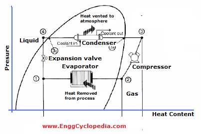
Refrigeration Cycle (Air Conditioning) - MATLAB & Simulink Pressure-Enthalpy Diagram This figure shows the fluid states in the refrigeration cycle plotted on a p-h diagram. The cycle points are compressor inlet, condenser inlet, liquid receiver inlet, thermostatic expansion valve inlet, and evaporator inlet. PDF Lab #8 Refrigeration - NCSU • Pressure-enthalpy diagram for R -12 • Pressure-enthalpy table for R -12 • Vapor compression refrigeration system • P, T, H, and phase changes in a vapor compression refrigeration cycle 2 . Goals of Lab • To get acquainted with a vapor-compression refrigeration system • To be able to use pressure-enthalpy diagrams and PDF How does basic refrigeration cycle work? If you are interested in learning how a refrigeration system works, it is helpful to understand from the Ph (Pressure Enthalpy) chart perspective. It makes our life much easier. This is how the refrigeration cycle diagram looks: Yeah, it seems complicated at first, but it will be easier to understand once I have explained the refrigeration ... PDF Refrigeration - NCSU • Vapor compression refrigeration system • Pressure-enthalpy diagram for refrigerants • Refrigerator, air conditioner, thermoelectric cooler, heat pump • Designation, choice, criteria for selection, and characteristics of refrigerants • Alternatives to vapor compression refrigeration system • Heat transfer in refrigeration applications
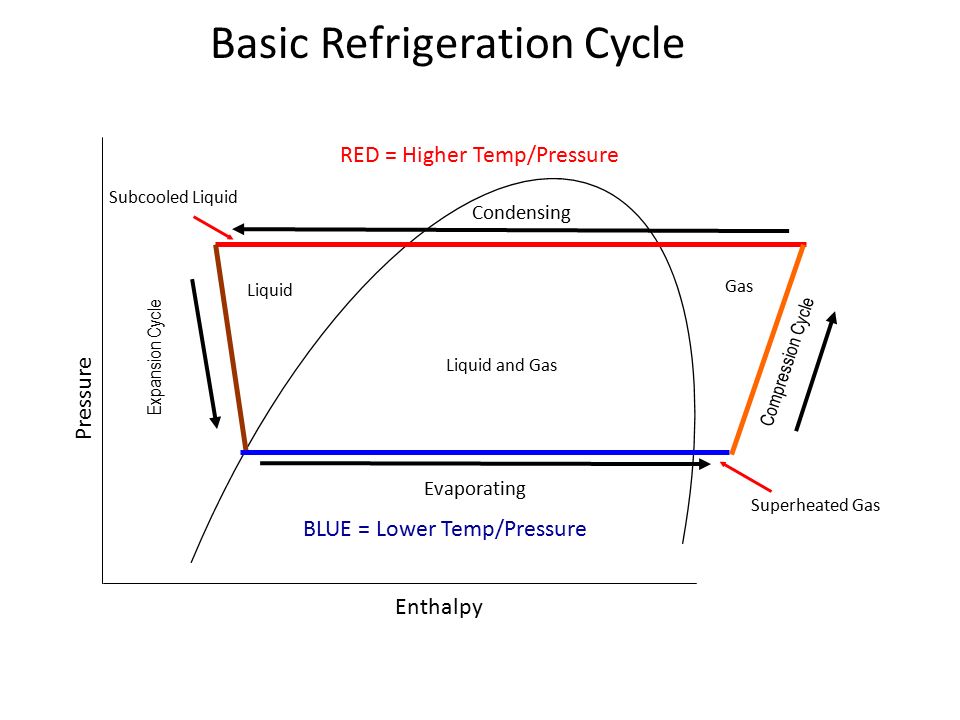
Pressure enthalpy diagram of a propane refrigeration cycle ... Pressure enthalpy diagram of a propane refrigeration cycle. This paper has applied thermodynamics principles to evaluate the reliability of 390m3/hr natural gas processing plant. The ... PDF Chart Pressure Enthalpy Diagram R134a 'basic refrigeration cycle central air conditioner and may 2nd, 2018 - the basic refrigeration cycle for beginners if we are interested in learning how a refrigeration system works it is helpful to understand from the ph pressure enthalpy chart perspective' 'refrigerants environmental properties engineering toolbox Pressure enthalpy diagram of the refrigeration cycle ... The Basic Refrigeration Cycle Mechanical refrigeration is accomplished by continuously circulating, evaporating, and condensing a fixed supply of refrigerant in a closed system. Evaporation occurs at a low temperature and low pressure while condensation occurs at a high temperature and high pressure. Pressure enthalpy chart r22 pdf - Australia Manuals User Guide Pressure enthalpy chart r22 pdf This case is to review the practical use of the Pressure-Enthalpy (P-H) diagram and the thermodynamic analysis of the refrigeration cycle using the P-H diagram; the Refrigerant Flow Diagram corresponding to the P-H Diagram. HVACR Refrigeration 141. Condensation and Condensers Instructional Assets . Handouts : Pressure-Enthalpy Chart - pdf Heat …

Category: Using Pressure Enthalpy Diagrams - FUNDAMENTAL ...
PDF Pressure Enthalpy Diagram R134a Air Conditioning Cycle pressure enthalpy diagram of the refrigeration cycle are. bme 421 refrigeration amp air conditioning debasmita mishra0. refrigerant selection with mollier chart ph diagram. pressure enthalpy as a service tool achr news. r134a chart enthalpy problems 4 7 a home refrigerator. figure 7 pressure enthalpy diagram for hfc 134a si units.
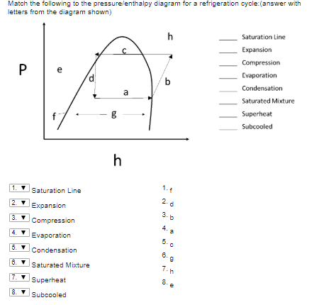
Solved Match the following to the pressure/enthalpy diagram ...
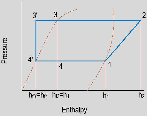
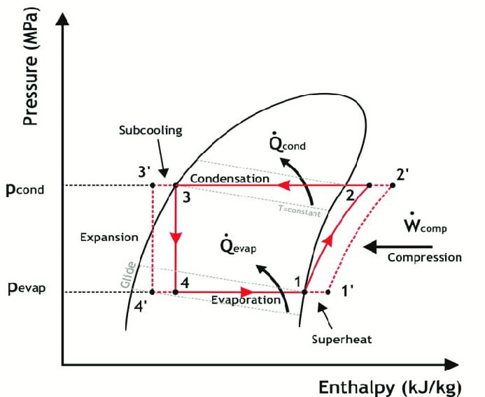
Refrigeration cycle diagram explained - Refrigeration ... Refrigeration cycle in the log p-h diagram. Green = compressor. Red = condenser. Yellow = expansion valve. Blue = evaporator. 1 - 2 polytropic compression to the condensing pressure (for comparison 1 - 2' isentropic compression) 2 - 2'' isobaric cooling, deheating of the superheated vapour. 2'' - 3' isobaric condensation.
Refrigeration and Heat Pump Systems VaporCompression ...
Refrigeration - Schematic and a Pressure Enthalpy Chart ... Learn refrigerant flow in a vapor compression system using a schematic of various components and a pressure enthalpy diagram.Please provide feedback on this ...

Enthalpy–entropy chart - Wikipedia
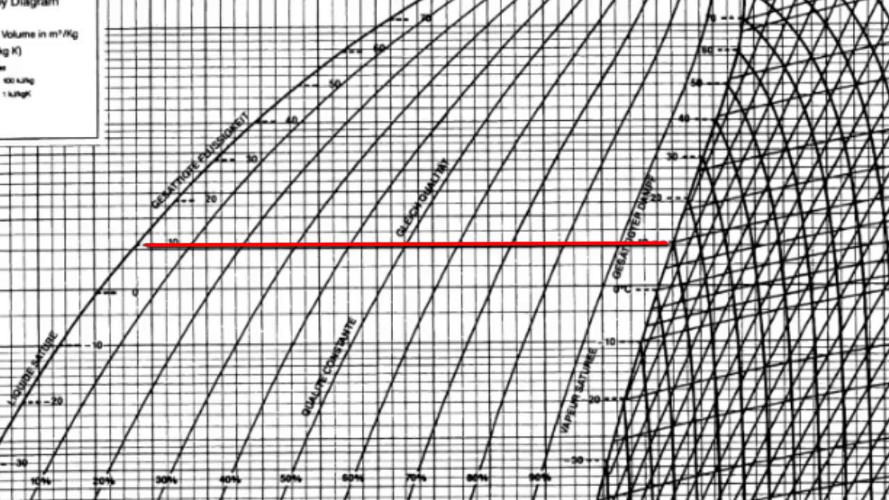
2.1 The pressure-enthalpy diagram - SWEP The pressure-enthalpy diagram (log P/h diagram) is a very useful tool for refrigerant technicians. First, an explanation of how the diagram is built up is given, and then its use is describ ed. Figure 2.1 shows the principle of a log P/h diagram, and indicates the refrigerant's various thermodynamic states.
Thermal Management Simulation Helps Auto A/C Shift to ...
What is Refrigeration Cycle? Basic, Diagram & Explanation ... The refrigeration cycle is the main basic cycle for all air conditioning and refrigeration equipment. In this chapter, we will discuss, basics of a refrigeration cycle, mainly vapor compression cycle, main concept, parts, components, working principle along with a real example, etc.

Refrigeration Cycles - Mech Engineering: Thermodynamics - UCL ...
PDF Refrigeration Cycle - Simon Fraser University M. Bahrami ENSC 461 (S 11) Refrigeration Cycle 3 Fig. 5-3: T-s and P-h diagrams for an ideal vapor-compression refrigeration cycle. 1-2: A reversible, adiabatic (isentropic) compression of the refrigerant.

Pressure-enthalpy diagram of the air-conditioning ...
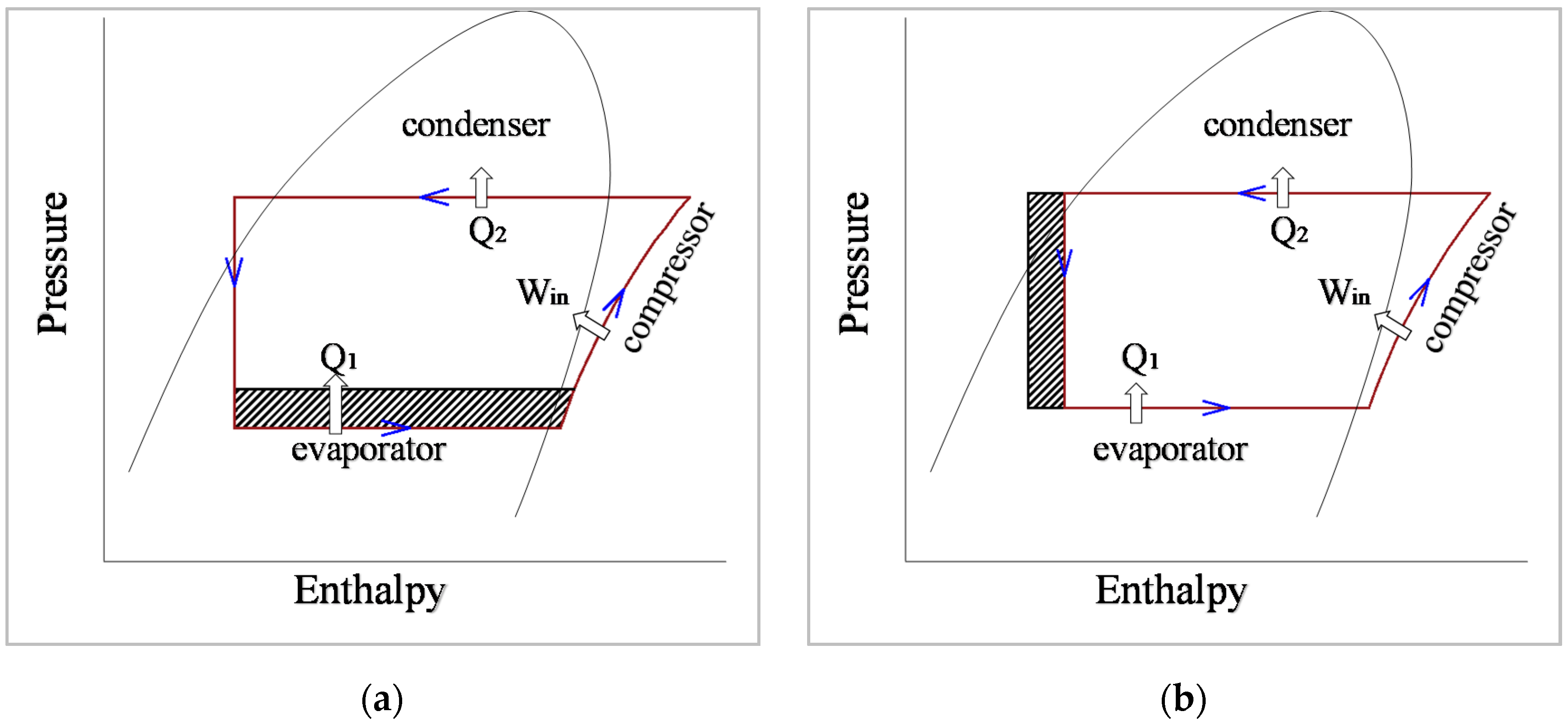
Pressure-Enthalpy (P-h) diagram of: (a) an ideal ... Pressure-Enthalpy (P-h) diagram of: (a) an ideal refrigeration cycle, (b) a typical refrigeration cycle [5]. Source publication +3 The Effect of Refrigerant Charge and Outdoor Temperature on the...
Refrigeration Basics - Definitions Part 2
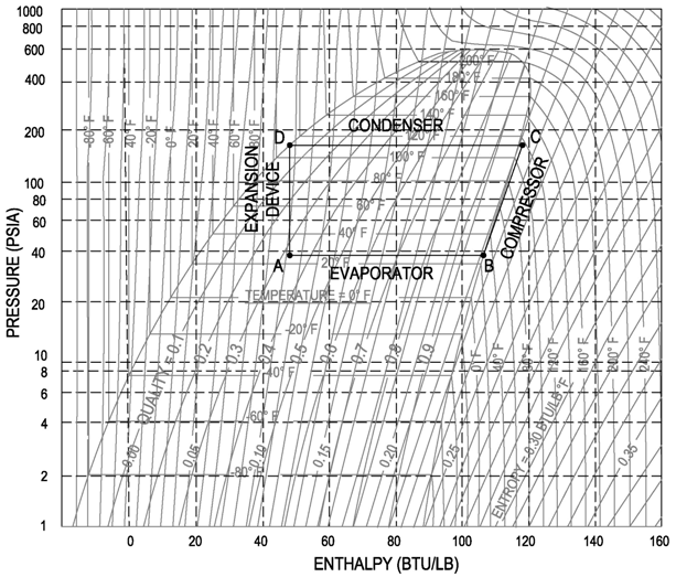
PDF Case 1: The Basics of Refrigeration Cycle P.H. Diagram ... From Figure 1-5, 1-7 and Figure 1-8, the enthalpy values of the various points of the refrigeration cycle can be obtained as the following: H 1= 102.42 BTU/LB H 2= 128.00 BTU/LB H 4= 112.31 BTU/LB H 5= 40.85 BTU/LB H 6= 40.85 BTU/LB
Refrigeration - Cycle for Ideal conditions on a Pressure Enthalpy Chart
The Pressure - Enthalpy Chart - Parker Sporlan refrigeration system should always be nearly filled with liquid refrigerant. Otherwise, its full potential as a heat transfer device will not be utilized. The pressure-enthalpy chart, as shown in Fig. 2, displays all the pertinent properties for a given refrigerant (in this example R22). The bubble to the left is the portion of the diagram where
JSRAE, Japanese Society for Refrigerating and AirConditioning ...
Refrigeration Cycles - Mech Engineering: Thermodynamics ... As a result a pressure drop occurs. The process is irreversible. Applying SFEE: Therefore, h2 = h1 Pressure-enthalpy chart The ideal vapour compression cycle consists of two constant pressure process and one constant enthalpy process. So in preliminary cycle calculations pressure-enthalpy diagrams are particularly useful.
Applied Sciences | Free Full-Text | Performance Study of ...
PDF Vapor Compression Refrigeration Cycle Figure 6- Pressure-enthalpy diagram of an ideal refrigeration cycle. Figure 7- L F D diagram of a real refrigeration cycle. To calculate the refrigerating capacity, i.e., heat transfer from low temperature source, 3 6 Å, the refrigerant mass flow rate I 6 should be known beforehand. The specific volume å for the refrigerant is read from the L

Heat Pump COP
Low Charge and the Pressure Enthalpy Diagram - FUNDAMENTAL ... The evaporator enthalpy dropped to 60 Btu/pound lowering the net refrigeration effect and the inlet volume to the compressor changed to .99 cubic foot per pound. The volume of flow, 8.7 cfm, calculated on the first diagram, is the compressors physical displacement because that was the design flow at the design inlet volume.

Pressure-enthalpy diagram for R-22 showing inlet and outlet ...
P-H Diagram, Pressure Enthalpy Diagram for Refrigeration ... In this video we explain the importance of the P-H diagram and how useful this is for the refrigeration cycle. Gauge and absolute pressure is also explained ...

Pressure-Enthalpy diagram for vapour compression cycle ...
PDF Pressure-enthalpy Charts and Their Use - Rses The most common type of pressure-enthalpy diagram is shown in Figures 1A through 1H. They show all five properties for a specific refrigerant in present-day use. Pressure is listed along the right and left borders in psia. Horizontal lines are constant pressure lines. Enthalpy is listed along the bottom and top of the diagram.
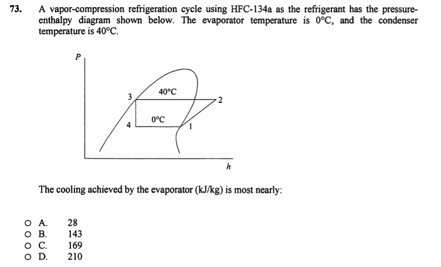
Solved 73. A vapor-compression refrigeration cycle using ...
Pressure-Enthalpy and the Variable Refrigerant Cycle - ppt ...

Figure 3 | Performance Evaluation of Refrigeration Units in ...
Thermodynamic Diagrams Spreadsheet

REFRIGERATION AND AIR CONDITIONING | Marine Inbox

Refrigeration - Schematic and a Pressure Enthalpy Chart

Refrigeration cycle diagram explained - Refrigeration - HVAC ...
Masterclass: Refrigeration Cycles - Part 3
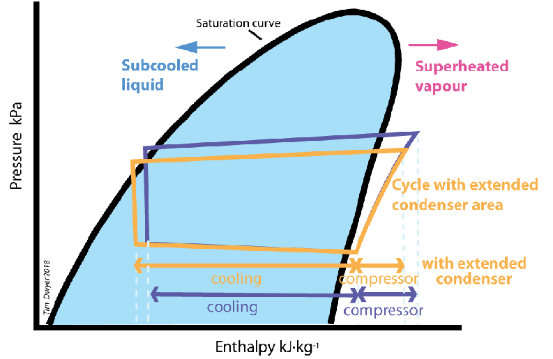
Module 128: Improving the performance of vapour compression ...

2.1 The pressure-enthalpy diagram - SWEP

Mollier Diagram - an overview | ScienceDirect Topics
Pressure Enthalpy Diagram, Limitations of Carnot Vapor ...

Compression Cycle - an overview | ScienceDirect Topics
PRESSURE-ENTHALPY CHARTS AND THEIR USE INTRODUCTION The ...
PRESSURE-ENTHALPY CHARTS AND THEIR USE INTRODUCTION The ...
Case – 1 The Basics of Refrigeration Cycle P-H Diagram ...
Lab #8 Refrigeration

b: Pressure – enthalpy - diagram for the refrigeration cycle ...
Typical Vapor Compression Refrigeration (VCR) cycle ...
JSRAE, Japanese Society for Refrigerating and AirConditioning ...

Pressure-enthalpy diagram for a standard vapor-compression ...
Pressure - Enthalpy Chart - Simple VCR System Questions and ...
Comparison of Actual and Theoretical Vapor Compression Cycle
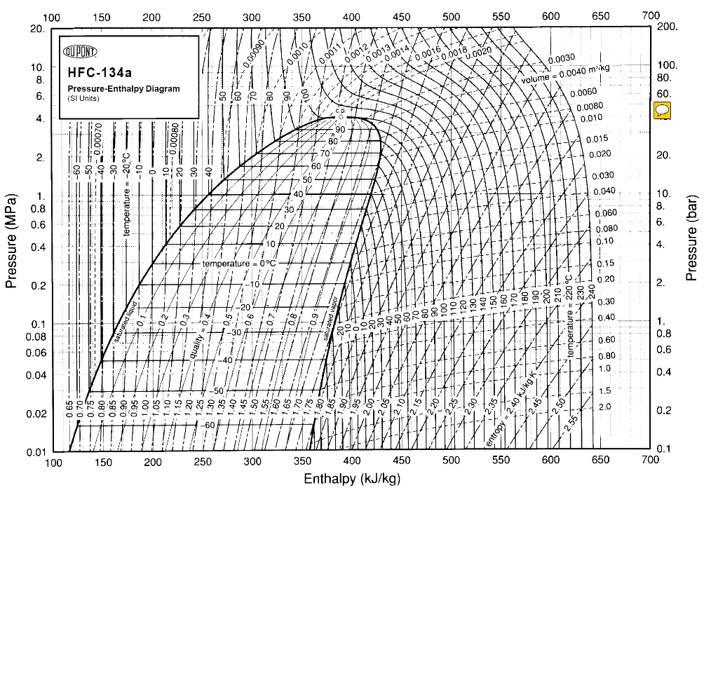
Solved 200 100 150 20 10 HFC-134a Pressure-Enthalpy Diagram ...
P-H Diagram Thermodynamics | HVAC and Refrigeration PE Exam ...
Refrigeration process, pressure/enthalpy diagram: Pressure ...

Energies | Free Full-Text | Functional Equations for ...

Pressure enthalpy diagram evaporation

Pressure enthalpy diagram of the refrigeration cycle ...


Komentar
Posting Komentar