43 ts diagram for air
Air T-s Diagram - EnTEs Air T-s Diagram : Specific Enthalpy. Air T-s Diagram : Specific Exergy. Air T-s Diagram : Exergy Ratio. Air T-s Diagram : Density. Air T-s Diagram : Constant Pressure Specific Heat. Air T-s Diagram : Constant Volume Specific Heat. Air T-s Diagram : Specific Heat Ratio. Air T-s Diagram : Velocity of Sound. Diesel Cycle - Process with P-V and T-S Diagram ... Diesel Cycle - Process with P-V and T-S Diagram. The diesel cycle was invented by Rudolph Diesel in 1893. He put forward an idea by which we can attain higher thermal efficiency, with a high compression ratio. All diesel engine works on this cycle. Diesel is used as fuel in this cycle as it can be compressed at higher compression ratio.
How to draw T-S diagram for simple air cooling cycle ... About Press Copyright Contact us Creators Advertise Developers Terms Privacy Policy & Safety How YouTube works Test new features Press Copyright Contact us Creators ...

Ts diagram for air
P-V and T-S Diagrams - NASA On the right of the figure we have plotted the temperature versus the entropy of the gas. This plot is called a T-s diagram. Lines of constant pressure curve from the lower left to upper right on a T-s diagram. A constant pressure process is called an isobaric process and this type of process occurs in the combustor of a gas turbine engine. T-S diagram of an air standard Diesel cycle model ... Download scientific diagram | T-S diagram of an air standard Diesel cycle model. from publication: Performance Analysis of a Diesel Cycle under the Restriction of Maximum Cycle Temperature with ... What is Carnot Cycle - pV, Ts diagram - Definition pV diagram of Carnot cycle. The area bounded by the complete cycle path represents the total work that can be done during one cycle. The Carnot cycle is often plotted on a pressure- volume diagram ( pV diagram) and on a temperature-entropy diagram ( Ts diagram ). When plotted on a pressure-volume diagram, the isothermal processes follow the ...
Ts diagram for air. What is Diesel Cycle - Processes with P-v and T-s Diagram P-v and T-s Diagram of Diesel Cycle Let the engine cylinder carry m kg of air at point 1. at this point let P1 and T1 and V1 be the pressure, temperature and volume of the air. Following are 4 stages of an ideal diesel cycle. The ideal diesel cycle consists of two adiabatic, constant pressure and constant volume processes. Thermal Efficiency - Brayton Cycle | Equation - Nuclear Power Brayton Cycle - Ts diagram. Isentropic compression - ambient air is drawn into the compressor, pressurized (1 → 2). The work required for the compressor is given by W C = H 2 - H 1. Isobaric heat addition - the compressed air then runs through a combustion chamber, burning fuel, and air or another medium is heated (2 → 3). What is Otto Cycle - P-V and T-S Diagram Easiest ... Note: For better explanation, while reading watch the P-V and T-S diagram everytime. 1. Process 1-2: Isentropic Compression. This process involves the motion of piston from TDC to BDC. The air that is sucked into cylinder during suction stroke undergoes reversible adiabatic (isentropic) compression. Diesel Cycle: Definition, Process, PV and TS Diagram ... When air is entered the piston moves TDC to BDC Bottom dead center. During the suction process, the inlet valve is open and the exhaust valve is closed. As you can see in the diagram. Compression Process: The compression is the second process in which the air is entered into the cylinder will be compressed along with the fuel.
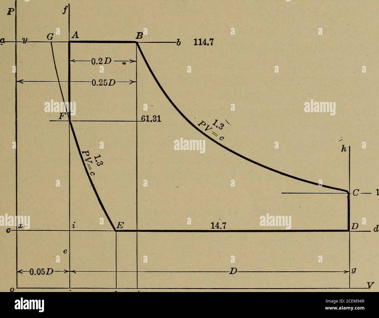
PDF Entropy-temperature and transmission diagrams for air Acknowledgment.-The original entropy-temperature diagram for air, Fig. 1, was designed by the writer several years ago. Recently, Mr. John A. Dent, Instructor in Mechanical Engineering, simplified the construction of this chart and improved it by the addition of a series of lines representing the curves of pv'= C, as shown by Fig. 2. ... Adiabatic Compresion: TS and HS Diagrams - Learn Thermo Ch 8, Lesson C, Page 10 - Adiabatic Compresion: TS and HS Diagrams. The purpose of a compressor is to convert shaft work into the ability to do PV or flow work. That means we raise the pressure of the working fluid. When we do this, the temperature increases, so we are also increasing the internal energy of the fluid. WINEGARD Gateway B. Air 360+ In Dome Install see page 8 for diagram If the compatible Air 360+ system was installed at the RV manufacturer and there isn’t a white circular Winegard cable access cap on the RV’s ceiling, the Gateway was meant to be installed inside the dome of the Air 360+. If [Part2] Reciprocating compression of air - Thermodynamics ... Isentropic efficiency on TS diagram The Isentropic efficiency is a comparison of the actual power output with the Isentropic case. Typical Isentropic efficiencies range from 70-90%.
Stirling Cycle: Efficiency with P-v and T-s Diagram The p-v and t-s diagrams of this cycle are shown in the figure. Let us now consider the four stages of the Stirling cycle. Let the engine cylinder contain m kg of air at its original position represented by point 1. At this point, let P1, T1, and V1 be the pressure, temperature, and volume of the air respectively. Phylum Platyhelminthes: Features, Diagram, Examples - Embibe Jan 18, 2022 · Phylum Platyhelminthes are a phylum of relatively simple bilaterian, unsegmented, soft-bodied invertebrates that belongs to kingdom Animalia. This phylum contains 13,000 species and include many free-living and parasitic life forms. Dual cycle: Definition, Process, Formula, Pv & Ts Diagram ... W 1−2 = Cv(T 1 − T 2) W 1 - 2 = C v ( T 1 - T 2) Process 2-3: Constant volume heat addition. For the isochoric process, Change in volume ( δv = 0 δ v = 0) ∴ W 2−3 = 0 ∴ W 2 - 3 = 0. Here temperature rises from T 2 T 2 to T 3 T 3. Hence change in internal energy is given by, Temperature Entropy (T-s) Diagram - Thermodynamics ... Temperature Entropy (T-s) Diagram A T-s diagram is the type of diagram most frequently used to analyze energy transfer system cycles. This is because the work done by or on the system and the heat added to or removed from the system can be visualized on the T-s diagram.
Dry Air - KCE - English
Example 7D - 3: Work, Efficiency and the T-S Diagram for ... Air contained in a piston-and-cylinder device undergoes a power cycle made up of three internally reversible processes. Step 1-2: Adiabatic compression from 20 psia and 570 o R to 125 psia: Step 2-3: Isothermal expansion to 20 psia Step 3-1: Isobaric compression a.) Sketch the process path for this power cycle on both PV and TS diagrams b.) Calculate T 3 in o F: c.) Calculate the boundary work ...
Otto and Diesel cycles: Which PV diagram is for SI and CI ...
FITNESS FOR AIR TRAVEL - Air Canada Call the Air Canada Medical Assistance Desk at 1-800-667-4732 and provide your booking reference in order to request extra seating for medical reasons and make any other necessary arrangements for your flight.
What is the h-s diagram for vapour compression refrigeration ...
Ts Diagram Of Air.pdf [en5zkdq9vpno] - idoc.pub Ts Diagram Of Air.pdf [en5zkdq9vpno]. ... THERMODYNAMIC PROPERTIES FIG. 2-5 Temperature-entropy diagram for air. [Landsbaum, Dadds, Stevens, et al., Am. Inst. Chem ...

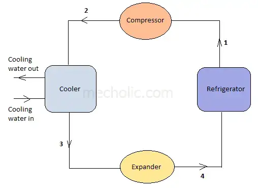
4. Aircraft Refrigeration System
TS diagram for the air standard Otto cycle | Download ... TS diagram for the air standard Otto cycle Source publication Constant Volume Combustion Cycle for IC Engines Article Full-text available Jan 2011 Jovan Dorić Ivan Klinar Marko Dorić This paper...

Carnot air standard cycle p-v and t-s diagram
Turbofan Explained- Thrust, Parts, T-S Diagram Turbofan: T-S Diagram. T-S diagram can easily explain the process of any engine that works with compression, expansion, heat addition, and heat rejection. With regards to the core flow, we assume that our turbofan undergoes Brayton cycle.

The T-s diagram of air-standard Otto cycle | Download ...
Carnot cycle: Definition, Formula, Pv and Ts Diagram ... Carnot cycle Pv and Ts diagram: Here, T 1 T 1 = T 4 T 4 = T L T L &. T 2 T 2 = T L T L = T H T H. The Processes in carnot cycle are as follows:-. Reversible adiabatic compression. Reversible Isothermal expansion ( Also known as Reversible Isothermal heat addition) Reversible adiabatic expansion.

Temperature–entropy diagram - Wikipedia
Scattering of Light: Meaning, Diagram, Examples - Embibe Jan 20, 2022 · Scattering of Light is basically the change in the direction of light. Lord Rayleigh was the first to study scattering of light from air molecules. He gave the relation, \(a = \frac{{AV}}{{r{\lambda ^2}}}\) where \(A\) is the amplitude of the incident light \(λ\) is the wavelength of the incident light \(a\) is the amplitude of the scattered light
The thermodynamic cycle shown in figure (Ts diagram) indicates
What is Carnot Cycle - pV, Ts diagram - Definition pV diagram of Carnot cycle. The area bounded by the complete cycle path represents the total work that can be done during one cycle. The Carnot cycle is often plotted on a pressure- volume diagram ( pV diagram) and on a temperature-entropy diagram ( Ts diagram ). When plotted on a pressure-volume diagram, the isothermal processes follow the ...
Applied thermodynamics for engineers. eal PV diagram, making ...
T-S diagram of an air standard Diesel cycle model ... Download scientific diagram | T-S diagram of an air standard Diesel cycle model. from publication: Performance Analysis of a Diesel Cycle under the Restriction of Maximum Cycle Temperature with ...

P H & T S Diagram for Sub Cooling (GATE) | Refrigeration & Air Conditioning | Thermodynamics |
P-V and T-S Diagrams - NASA On the right of the figure we have plotted the temperature versus the entropy of the gas. This plot is called a T-s diagram. Lines of constant pressure curve from the lower left to upper right on a T-s diagram. A constant pressure process is called an isobaric process and this type of process occurs in the combustor of a gas turbine engine.

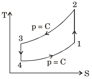
Air Refrigerator Working On Bell-Coleman Cycle with PV and TS ...
Air Refrigerator Working On Bell-Coleman Cycle with PV and TS ...

Regenerative Air Cooling System

T-S diagram of the improved model heat pump cycle for R134a ...

Ts-diagram showing a transcritical R744 air-conditioning ...

Air T-S Diagram | PDF
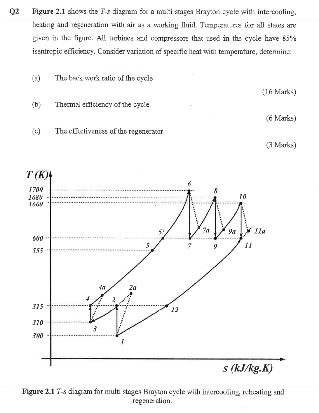
Solved Q2 Figure 2.1 shows the T-s diagram for a multi ...

TS Diagram of Air | PDF
Moist Air - the Mollier Diagram

Ideal Rankine Cycle

T-s diagram for the Brayton cycle with recuperator ...

Air cycle combined heating and cooling for the food industry ...

3. T-s diagram for the two-stage air compressor | Download ...
Air in a piston/cylinder goes through a Carnot cycle with the ...

Energy Analysis Software

Otto cycle p-V and T-s diagram | Thermodynamics, Physics ...

Boot-strap Evaporative Air Cooling System
Refrigeration and Heat Pump Systems - ppt video online download

T-s-Diagram of Huntorf under reversibility assumptions ...
Applied Sciences | Free Full-Text | Influence of Frost Growth ...
Solved 1. Figure 1 shows the P-V and T-s diagrams for an ...

Chapter 10a: a) Air - Water Vapor Mixtures (updated 5/10/10)

T-s-Diagram of Huntorf and McIntosh CAES processes Several ...

Heavy Water T-s Diagram
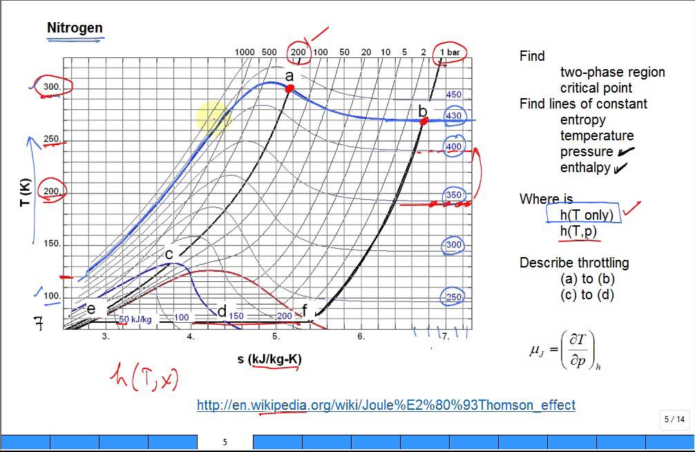
Explain Joule Thomson effect with Nitrogen TS diagram

Steam - Wikipedia

P - H & T - S Diagram for Super Heating | Refrigeration & Air Conditioning | Power Engineering|
Ideal Rankine Cycle

White Brook Solutions
![Solved] The P-v diagram of an air-standard Ericsson cycle ...](https://s3.amazonaws.com/si.question.images/image/images13/962-P-T-H-A-1-L(2288).png)
Solved] The P-v diagram of an air-standard Ericsson cycle ...

Air T-s Diagram

The Limitations of Single Stage Air Compressors. - Bright Hub ...

MAE115 Quizzes Flashcards & Practice Test | Quizlet


Komentar
Posting Komentar